background image

TR-RT LED lighting controllers - User Manual

12.4

Fatal error codes

Error number

Reason

Err 44

The TR-RT is too hot. The TR-RT has a thermal
cutout which operates around 65°C to 70°C,
depending on conditions.

Err 40, Err 41
Err 45

One channel is outputting more current than
expected.

Err 47

Internal protection has prevented too much heat in
the output driver.

12.5

Event codes

Event messages are sent when a light is connected or an error occurs. The
format of these is:

Evt<channel>,<event code>;

These event messages are only sent after the

GT1

command has been

sent.

Event number

Reason

1 to 127

An error has occurred. The error code is given by
the event number.

128

A light has been connected and is working.

129

A light has been connected but doesn’t have a
current or voltage rating.

130

An over temperature error occurred.

131

An over current error occurred.

132

An error has occurred while autosensing the rating
of a light.

138

SafePower trainup has completed.

139

SafePower trainup has failed or been cancelled.

140

In switch output mode, the light has been turned
off because the duty cycle is too high.

40

Содержание TR-RT Series

Страница 1: ...TR RT LED Lighting Controllers Issue 002 User manual www gardasoft com ...

Страница 2: ...cause any dangerous situation or significant financial loss to occur Deliberate acts of endangerment and vandalism are not covered by this document and must be considered by the installer While care has been taken in the preparation of this document Gardasoft Vision Ltd and Gardasoft Products Ltd will not accept any liability for consequential loss of any kind except those required by law All trad...

Страница 3: ...ons 13 5 2 Electrostatic discharge 14 6 Connections 15 6 1 Power supply 15 6 2 Lighting output 15 6 3 Trigger inputs 17 6 4 12V Power output 18 6 5 Ethernet connection 18 6 6 Serial connection 18 6 7 Connectors 18 7 General description 19 7 1 Output modes 19 7 1 1 Continuous output switched output selected output 20 7 2 Pulsed output 20 7 3 Fault detection 21 7 4 Light auto sensing 21 7 5 Cold sta...

Страница 4: ...neral setup page 29 11 Command configuration 30 11 1 Ethernet configuration TR RT220 TR RT420 30 11 2 RS232 configuration TR RT260 TR RT460 30 11 3 Command structure 30 11 3 1 General commands 31 11 3 2 Command summary 36 12 Reference information 37 12 1 Specification 37 12 2 Restrictions 38 12 3 Error codes 39 12 4 Fatal error codes 40 12 5 Event codes 40 ...

Страница 5: ...e TR RT up to a power supply as described in Section 6 Connections Read Section 8 Lighting setup If your lights are triniti enabled connect them to the controller and switch on If your lights are not triniti enabled enter the current or voltage rating of the lights and then connect the lights Set up the TR RT for the desired operation as described in the configuration sections Section 10 Webpage c...

Страница 6: ... TR RT420 4 Yes No No TR RT460 4 No Yes No TR RT420F 4 Yes No Yes TR RT460F 4 No Yes Yes 1 2 GigE Vision The TR RT range of controllers is GigE Vision v2 0 compatible This means that any compatible GigE Vision client image processing software allows the user to view and change controller settings GigE Vision is an industry standard protocol running on Ethernet which provides easy configuration and...

Страница 7: ...ause a burn if touched Place in a position where personnel cannot accidentally touch it and ensure there is a free flow of air around the unit 2 2 Electrical The TR RT produces high energy pulses Take care to connect the outputs correctly and protect the output wiring and load from any short circuits When switched off energy remains stored in the TR RT for about 15 seconds The TR RT does not have ...

Страница 8: ...ation is for guidance only Installers must perform their own risk assessment specific to each installation While Gardasoft Vision Ltd has taken every care in the preparation of this advice Gardasoft Vision Ltd and Gardasoft LLC accept no liability for damages of any kind except those required by law Deliberate acts of endangerment and vandalism are not covered by this document and must be consider...

Страница 9: ...ehäuse der TR RT mehr als 65 C erreichen und folglich bei Berührung Verbrennungen verursachen Positionieren Sie sie an einem Ort an dem sie nicht aus Versehen von Personal berührt werden und an dem die Luft um die Einheit zirkulieren kann 3 2 Elektrik Die TR RT produziert energiereiche Pulse Achten Sie darauf die Ausgänge korrekt anzuschließen und die Ausgangsverdrahtung und die Verbraucher vor Ku...

Страница 10: ...en 3 4 Haftungsausschluss Diese Angaben dienen lediglich der Orientierung Der Monteur muss für jede Installation eine eigene spezifische Risikobewertung durchführen Gardasoft Vision hat bei der Zusammenstellung dieser Empfehlungen größtmögliche Sorgfalt walten lassen Gardasoft Vision und Gardasoft LLC übernehmen über das gesetzlich erforderliche Maß hinaus keine Haftung für Schäden aller Art Vorsä...

Страница 11: ...asser 65 C ce qui est suffisant pour occasionner des brûlures en cas de contact Assurez vous que le personnel ne peut pas y toucher accidentellement et que l air circule autour de l unité 4 2 Électricité Le TR RT produit de fortes pulsations énergétiques Assurez vous que les sorties sont bien connectées et que les fils de sortie et les charges sont bien à l abri d éventuels courts circuits Une foi...

Страница 12: ...l pourra en être altérée 4 4 Clause de non responsabilité Ces informations sont seulement à titre indicatif Les installateurs doivent établir leur propre évaluation de risques pour chaque installation Gardsoft Vision a préparé minutieusement ces conseils mais Gardasoft Vision et Gardasoft LLC déclinent toute responsabilité concernant les dommages de toute nature à l exception de ceux requis par la...

Страница 13: ... available for mounting the TR RT on a DIN rail 5 1 Environmental considerations The TR RT enclosure is a fire enclosure as long as it is mounted so that none of the connectors are facing downwards If a fire enclosure is used the enclosure should be metal or plastic with a flammability rating of UL94 V1 or better with no holes below or to the sides of the TR RT when mounted Cable entries below the...

Страница 14: ...rostatic discharge Electrostatic discharge ESD can damage equipment and impair the electrical circuitry inside your TR RT ESD damage occurs when electronic components are improperly handled and can result in complete or intermittent failures On the TR RT this is relevant only to the trigger connections and power input 14 ...

Страница 15: ...e ambient temperature The external power supply must be capable of supplying at least the average output power for all active channels We recommend you use a regulated power supply with 100 short circuit protection If however a non regulated power supply is used then the maximum ripple voltage of the power supply must not exceed 10 of the DC voltage Route the low voltage and mains wiring separatel...

Страница 16: ...s They are identified as Channels in the illustrations showing their location The lighting and triniti connector is shown below viewed from outside the controller with the top cover uppermost The lighting output connections and triniti sense lines must not be commoned to any other controllers or grounded in any way The connectors fitted to a TR RT2xx and a TR RT4xx series controller are shown in t...

Страница 17: ...rawing a minimum of 3mA The table below describes the pin allocations for the TR RT controllers trigger connectors Note All TR RT controllers are fitted with Connector ET12 Connector ET34 is present on the TR RT4xx series controllers Pin Connector ET12 Connector ET34 1 TRIG1 TRIG3 2 TRIG1 TRIG3 3 TRIG2 TRIG4 4 TRIG2 TRIG4 17 ...

Страница 18: ...d to TR RT260 and TR RT460 controllers is a standard 9 way female D type A standard straight through cable can be used to connect the controller to a PC serial port The communications port settings are 115Kbaud no parity 8 data bits and 1 stop bit The pin allocation for the serial connector is shown opposite 6 7 Connectors The TR RT packaging includes mating connectors for the power supply input t...

Страница 19: ...er input is used as a trigger The delay from trigger to pulse the pulse duration and the brightness can be set Switched In switched mode a trigger input is used to switch the output current on and off The output is only enabled when the trigger input has a voltage on it Selected In selected mode a trigger input is used to select between two different intensities Tandem It is possible to connect in...

Страница 20: ...ed from 0 to 100 of full brightness 7 2 Pulsed output The output is off by default When the TR RT is triggered it waits for a delay and then pulses the output The delay pulse width retrigger delay and pulse intensity are all configurable Retrigger delay is the minimum allowed time from one trigger to the next Any triggers that happen too soon after the previous trigger are ignored The retrigger de...

Страница 21: ...cancel the error see Section 11 Command configuration The TR RT controller re senses the light Error Reason 34 37 Internal power dissipation is too high Output turned off 35 43 Output current to lighting is too low The light is open cir cuit or there is not enough supply voltage for the reques ted output current 36 If the output voltage is too low the controller detects that the output is short ci...

Страница 22: ...or the voltage rating Err 23 Current output is not what was expected The controller might need calibrating Err 23 The power rating of the light exceeds the maximum power rating 7 5 Cold start You can clear the TR RT configuration to its default settings this clears the lighting ratings and sets all channels to 50 brightness continuous operation You can do this by sending the CL command using Ether...

Страница 23: ...dules if a voltage and current rating is given use the current rating If a voltage and wattage rating is given use the voltage rating Otherwise use the current rating For homemade lights using single LEDs or arrays of LEDs use the current rating from the LED datasheet You can set the current rating from 0 01A to 3A in steps of 0 01A and you can set the voltage rating from 12V to 36V in steps of 1V...

Страница 24: ...T is usually connected to a network switch hub or router but you can connect it directly into the network port on a PC using a crossover cable 9 2 IP Address The TR RT needs an IP address to communicate over Ethernet There are two ways to get an IP address either programmed into the unit or using DHCP For DHCP mode the TR RT acquires its IP address subnet mask and gateway address from a DHCP serve...

Страница 25: ...y be an alternative fixed IP address on the Alternative Configuration tab You can find out what IP address is being used by a PC at any time by following the steps below i Go to the Control Panel ii Select Network Connections iii Right click on Local Area Connection Select Status iv Select the Support tab The IP address is displayed 9 2 2 Fixed IP address When using a fixed IP address you must ens...

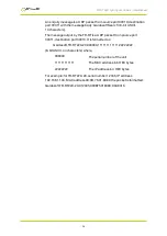
Страница 26: ... source port 30311 destination port 30310 It is formatted as Gardasoft TR RT220 20 000000 111111111111 22222222 8 bit ASCII 44 characters where 000000 The serial number of the unit 111111111111 The MAC address in 6 HEX bytes 22222222 The IP address in 4 HEX bytes For example for TR RT220 20 serial number 12345 IP address 192 168 1 103 MAC address 00 0B 75 01 80 99 the packet is formatted Gardasoft...

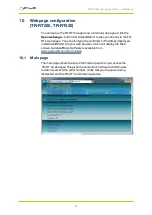
Страница 27: ...e the controller s IP address displayed in GardasoftMaint into your web browser which will display the Main screen GardasoftMaint software is available from www gardasoft com Downloads 10 1 Main page The main page shown below is the first to open when you access the TR RT s webpages This gives the controller s hardware and firmware revision levels and the serial number It also tells you the power ...

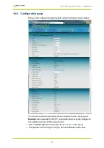
Страница 28: ... below You can set up all the parameters for each output channel Pressing the Submit button updates the TR RT configuration and saves the changes to non volatile memory On this page you can View the triniti light information see Section 10 2 1 triniti status Change the current rating for the light but use this feature with care 28 ...

Страница 29: ...al number and you can create your own name for the light Dynamic factors concerning the light are fed back to the TR RT such as its temperature usage and age This information is used by the TR RT to adjust the output current to ensure the light provides consistent levels of illumination throughout its lifetime Information about the triniti chip is also returned such as serial number and software v...

Страница 30: ...haking A carriage return ASCII 13 character should be sent to terminate the command line 11 3 Command structure Communication consists of commands sent by the host controlling PC All output generated by the command is returned in reply UDP or TCP IP packets The last character sent is greater than symbol Once this is received the host knows that the command has been completed We recommend that the ...

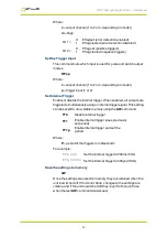
Страница 31: ...11 3 1 General commands Any changes you make using Ethernet commands are not saved permanently until you send the AW command Report the version of firmware running in the TR RT This command returns the firmware version For example VR returns TR RT420 20 HW02 V031 Set the rating of a light This command sets the current or voltage rating for a light If a current rating is being set then the voltage ...

Страница 32: ...ting in percent t 0 to s Set pulse mode The output can be set up to pulse on a trigger input The delay from trigger to the start of the pulse the length of the pulse and the brightness are configurable An error is generated if the brightness setting requires a current greater than 20A or if the combination of pulse width and setting is not allowed RTc p d s RTc p d s r Where c output channel 1 to ...

Страница 33: ...led all outputs are triggered simultaneously using an internal trigger signal This setting can be saved to non volatile memory using the AW command TT0 Disable internal trigger TT1 Enable internal trigger uses previously set period TT1 p Enable internal trigger and set the period Where P period of the triggers in milliseconds For example TT1 200 Set the internal trigger to 200ms 5Hz TT1 500US Set ...

Страница 34: ... 000A RA0 000A CH2 MD0 S 50 0 0 0 DL1 000ms PU1 000ms RT 0 0us IP2 FL0 CS0 000A RA0 000A Where CH Channel number MD Mode 0 continuous 1 pulse 2 switched 3 select S Brightness percentage settings 1st setting used in all modes 2nd setting only used for select mode DL Pulse delay PU Pulse width RT Retrigger delay IP Input trigger set using the RP command FL Flags set using the RE command CS Rating of...

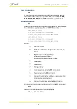
Страница 35: ... c the channel number 1 to 2 or 4 or 0 for no channel e event value see Section 12 5 Event codes Clear any Errors GR If Ethernet messages are not enabled the last event or error number can be read by this command Any error displayed on the unit is cleared so if there was a lighting error the TR RT resumes auto sensing on that channel The reply is in the same form as the GT command above If there a...

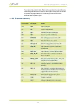
Страница 36: ...EY65 66 Set webpage password to AB VR VR Read the firmware version VL VL1 0 0 5 Set the rating of channel 1 to 0 5A RS RS2 65 Set channel 2 to 65 brightness continuous RW RW1 50 Set channel 1 to 50 switch mode RU RU1 75 25 Set channel 1 to selected mode at 75 and 25 RT RT2 3 4 50 Set channel 2 to 3ms pulses delayed by 4ms at 50 brightness RP RP1 2 Output channel 1 is triggered using output 2 RE RE...

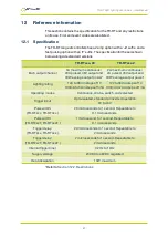
Страница 37: ...age output power Lighting rating 12V to 36V in steps of 1V 100mA to 3A in steps of 5mA 12V to 36V in steps of 1V 100mA to 2A in steps of 1mA Operating modes Continuous strobe switch and selected Trigger input Opto isolated standard or inverted operation 3V to 24V Pulse width TR RT2xx TR RT4xx 20 microseconds to 1 second Repeatable to 0 1 microseconds Pulse width TR RT2xxF TR RT4xxF 1 microsecond t...

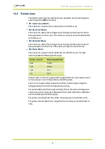
Страница 38: ...A B 4 Pulse Mode The maximum output current is 20A 2A for a TR RTxxx 2 For high current pulses the following limits apply Pulse current Pulse length limit 20A 100μs 12A 400μs 10A 1ms 5A 3ms Pulses of 2A or more for pulse widths longer than 2ms may cause an error or have a lower current towards the end of the pulse The minimum pulse delay is about 2μs When overdriving or using the retrigger delay t...

Страница 39: ...orrupt The configuration has been cleared Err 9 20 Could not save settings to EEPROM Err 21 22 23 Sensing error See Section 6 2 Light auto sensing Err 27 Can t read Ethernet settings from EEPROM so these may be incorrect Err 34 47 Internal power dissipation is too high Output turned off Err 35 Output current to lighting is too low Err 43 The requested output current requires too high a voltage Err...

Страница 40: ...rmat of these is Evt channel event code These event messages are only sent after the GT1 command has been sent Event number Reason 1 to 127 An error has occurred The error code is given by the event number 128 A light has been connected and is working 129 A light has been connected but doesn t have a current or voltage rating 130 An over temperature error occurred 131 An over current error occurre...

Страница 41: ...TR RT LED lighting controllers User Manual This page is left blank for your notes 41 ...

Страница 42: ...ber 2016 Copyright 2016 Gardasoft Vision Ltd Gardasoft Vision Ltd Trinity Court Buckingway Business Park Cambridge CB24 4UQ UK tel 44 1954 234970 fax 44 1954 231567 Gardasoft LLC Oak Ridge Road Weare New Hampshire 03281 USA tel 1 603 657 9026 www gardasoft com ...

Отзывы: