5
FocalPoint™ Receivers Gateway Installation & Operation Manual - P/N: 53251:Rev: A 9/8/09
Table of Contents
Section 1 About Receivers Gateways..................................................................................... 7
1.1: FPT Receivers Gateway Description .............................................................................................................7
1.2: FPT Receivers Gateway System Architecture ...............................................................................................7
Figure 1.1 Receivers IP Network Architecture Diagram .......................................................................7
Figure 1.2 Receivers Telephone Architecture Diagram .........................................................................8
1.3: Agency Listings .............................................................................................................................................8
1.3.1: Compliance..........................................................................................................................................8
1.3.2: Installation ...........................................................................................................................................8
1.4: Environmental Requirements ........................................................................................................................9
1.5: Related Documentation .................................................................................................................................9
Section 2 Digital Receivers Installation and Configuration ................................................ 11
2.1: Digital Receiver Setup Guidelines...............................................................................................................11
2.1.1: Automatic Updates ............................................................................................................................11
2.2: ADEMCO 685 Setup...................................................................................................................................12
2.2.1: 685 Cable Configuration ...................................................................................................................12
Figure 2.1 ADEMCO 685 Cable Connections .....................................................................................12
2.2.2: 685 Jumper Settings ..........................................................................................................................12
2.2.3: 685 DIP Switch Settings....................................................................................................................12
2.2.4: 685 Supported Formats......................................................................................................................12
2.2.5: 685 Parallel Printer Requirements.....................................................................................................12
2.2.6: 685 Communication Settings ............................................................................................................12
2.2.7: 685 Device Addressing and Supervision...........................................................................................12
2.2.8: 685 Device Addresses Reported by the Gateway..............................................................................13
2.2.9: 685 Site IDs .......................................................................................................................................13
2.2.10: 685 Device IDs ................................................................................................................................13
2.3: Radionics D6600 Setup ...............................................................................................................................14
2.3.1: D6600 Description.............................................................................................................................14
Figure 2.2 Radionics D6600 Receiver Application Example ..............................................................14
2.3.2: Supported Formats.............................................................................................................................14
2.3.3: D6600 Serial Communication Connection........................................................................................15
Figure 2.3 D6600 To Gateway Serial Connection ...............................................................................15
2.3.4: D6600 Setup ......................................................................................................................................15
Table 2.1 D6600/Receivers Gateway Configuration Settings..............................................................15
2.3.5: D6600 Configuration.........................................................................................................................16
2.3.6: D6600 Operation and Event Handling ..............................................................................................16
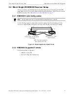
2.4: Silent Knight 9500/9800 Receiver Setup ....................................................................................................17
2.4.1: 9500/9800 Cable Configuration ........................................................................................................17
Figure 2.4 Silent Knight Serial Cable Pinouts......................................................................................17
2.4.2: 9500/9800 Supported Formats ..........................................................................................................17
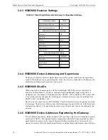
2.4.3: 9500/9800 Receiver Settings .............................................................................................................18
Table 2.2 Silent Knight/Receivers Gateway Configuration Settings ...................................................18
2.4.4: 9500/9800 Device Addressing and Supervision................................................................................18
2.4.5: 9500/9800 Site IDs ............................................................................................................................18
2.4.6: 9500/9800 Device Addresses Reported by the Gateway...................................................................18
2.4.7: 9500/9800 Device IDs .......................................................................................................................19
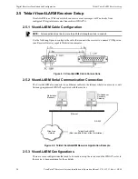
2.5: Teldat VisorALARM Receiver Setup ..........................................................................................................20
2.5.1: VisorALARM Cable Configuration ..................................................................................................20
Figure 2.5 VisorALARM Cable Connections ......................................................................................20
2.5.2: VisorALARM Serial Communication Connection ...........................................................................20
Figure 2.6 Teldat VisorALARM Receiver Application Example........................................................20
2.5.3: VisorALARM Configurations...........................................................................................................20
2.5.4: VisorALARM Supported Formats ....................................................................................................21
2.5.5: VisorALARM Communication Settings ...........................................................................................21


