Galvin Engineering TCS9J150C Скачать руководство пользователя страница 5


© Galvin Engineering Pty Ltd 


Product Installation Guidelines 

Document No.: 001.00.10.16 

Version 1, 4 November 2022, Page 

5

 of 

7


5. 

Fit grab rail into wall mount plate and tighten 
lock nut firmly.


6. 

Screw flange cover to wall mount plate.


7.  Cradle Installation 

Fit the shower cradle to the grab rail as shown. 

Position the cradle as desired then tighten the 
cover of the cradle. 


8.  Connect  Flange Wall Outlet Elbow 

Apply thread tape to wall spud. When applying 
thread tape or sealant to the wall spud, ensure 
the opening is not obscured. Failure to do so 
may restrict or block the flow restrictor, 
affecting the flow of water. 

Remove spigot by loosening grub screw in 
elbow.  

Fit spigot to wall spud, ensuring the flow 
regulator is in place and not damaged when 
tightening the spigot. 


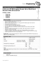
9.  Connect  Flange Wall Outlet Elbow 

Fit elbow over spigot and secure with grub 
screw. 

Using 2.5mm hex key supplied, tighten 5mm 
grub screw.


     10.   Check Shower for correct operation 
             and leaks 

-    Connect hose and shower head ensuring the 
connection is secured, then turn on water supply. 
Check for any leaks. 


Hex Key 

Elbow 

Grub Screw 

Spigot 

Flow Regulator 

Содержание TCS9J150C

Страница 1: ...event back siphonage 80 150 mm CliniLever contra rotating lever handles make showering easier for users with disabilities or limited hand mobility Handles are finished in bright chrome plate finish for added durability and easy cleaning Suitable for installation and will assist in compliance to AS1428 1 Design for access and mobility General requirements for access New building work IMPORTANT All ...

Страница 2: ... Galvin Engineering Pty Ltd Product Installation Guidelines Document No 001 00 10 16 Version 1 4 November 2022 Page 2 of 7 PRE INSTALLATION MOUNTING DETAILS SHOWER ...

Страница 3: ...ion Guidelines Document No 001 00 10 16 Version 1 4 November 2022 Page 3 of 7 MOUNTING DETAILS WALL TOP ASSEMBLY Wall body Wall body must be G5 8 FI and body should be between 0 and 15mm behind the finished wall surface 80 150 mm Wall Top Assembly ...

Страница 4: ... Other type of screws may rust and void warranty When marking out the grab rails use centre base holes of flange protector When marking out corner grab rails follow the fixing guide lug diagram shown above to suit grab rail orientation 1 Install straight grab rails including the horizontal section of any grab rail if applicable as per AS 1428 1 800 810mm from floor to top of rail Make sure the wal...

Страница 5: ...ead tape or sealant to the wall spud ensure the opening is not obscured Failure to do so may restrict or block the flow restrictor affecting the flow of water Remove spigot by loosening grub screw in elbow Fit spigot to wall spud ensuring the flow regulator is in place and not damaged when tightening the spigot 9 Connect Flange Wall Outlet Elbow Fit elbow over spigot and secure with grub screw Usi...

Страница 6: ...amic cartridge into the valve body by hand tighten using a 17mm spanner Refit threaded sleeve and spindle The turn ceramic head part MUST be fitted into the wall body prior to refitting the threaded sleeve and spindle DO NOT tighten cartridge by using the spindle or the threaded sleeve 2 Fit wall flange Ensure o ring is fitted to the bottom of the wall flange and then hand tighten the wall flange ...

Страница 7: ...makes no other warranties express or implied Galvin Engineering Pty Ltd hereby specifically disclaims all other warranties express or implied including but not limited to the implied warranties of merchantability and fitness for a particular purpose Galvin Engineering Pty Ltd products are covered under our manufacturer s warranty available for download from www galvinengineering com au Galvin Engi...

Отзывы: