


© Galvin Engineering Pty Ltd
Product Installation Guidelines
Document No.: 001.00.10.16
Version 1, 4 November 2022, Page
4
of
7
INSTALLATION - SHOWER
INSTALLATION COMPLIANCE: Galvin Engineering products must be installed in accordance with these
installation instructions and in accordance with AS/NZS 3500, the PCA and your local regulatory requirements.
Water and/or electrical supply conditions must also comply to the applicable national and/or state standards.
Failing to comply with these provisions shall void the product warranty and may affect the performance of the
product.
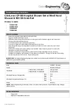
WARNING: Install with stainless steel
304 or 316 screws. Other type of
screws may rust and void warranty.
When marking out the grab
rails, use centre base holes of
flange protector.
When marking out corner grab rails
follow the fixing guide lug diagram
shown above to suit grab rail
orientation.
1.
Install straight grab rails including the
horizontal section of any grab rail (if
applicable) as per AS 1428.1, 800-810mm
from floor to top of rail. Make sure the wall
surface is flat and free from contaminants.
2.
For straight grab rails, position the flange
protector guide lugs either vertical or
horizontal.
3.
Remove flange protector from grab rail
flange. Align guide lug marks from step 2 and
mark wall through base holes to pinpoint
screw holes.
4.
Fit dress ring if applicable. Drill spot
marks with 7mm bit. Screw wall mount
plate to wall. Ensure screws engage wall
stud or other solid substrate.