Rev 1.1
Galaxy 1 Proprietary Information
5
1.3
Interfaces and Indicators
1.3.1
Indicator Panel
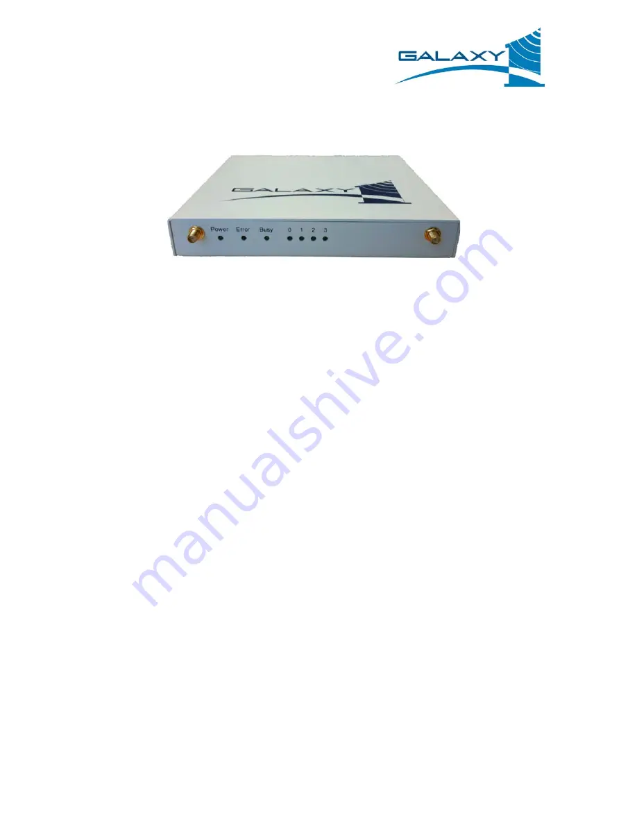
Figure 1: G1 IG Indicator Panel
G1 IG indicators:
•
0, 1, 2, 3 – Ethernet activity indicators illuminate when a Ethernet link is present and flash when
Ethernet traffic is sent or received on the interface. 0, 1, 2, and 3 correspond with the eth0,
eth1, eth2, and eth3 Ethernet interfaces on the port panel.
•
Busy – The busy indicator illuminates when the G1 IG is executing commands from the router’s
internal storage media. It behaves much like a computer’s drive activity indicator.
•
Error – The error indicator illuminates when the G1 IG is experiencing an error condition.
•
Power – The power indicator is illuminated when the G1 IG device is powered on.
G1 IG Wi-Fi antenna – The G1 IG antennae are a pair of Reverse Polarity Threaded Female SMA type
jacks mounted on the front of the indicator panel.
1.3.2
Port Panel
Power port – The G1 IG power port is a 5.5mm outside diameter 2.5mm inner diameter industry
standard barrel jack. The G1 IG requires approximately 15W and accepts power in the range of 9VDC to
26VDC. The power port pin out is as follows:
•
Pin – DC + (9V-26V)
•
Barrel – Ground
G1 IG ports:
•
eth0, eth1, eth2, eth3 – In the default configuration the eth0, eth1, and eth2 ports behave as
Ethernet LAN ports and the eth3 port behaves as an Ethernet WAN port. These ports are
10/100 Fast Ethernet interfaces with an auto-crossover (auto-MDIX) capability. Auto-crossover
means that either regular or crossover Ethernet cables will work with the ports.
•
Console – In the default configuration the console port allows users to locally attach to the
command line configuration interface of the G1 IG. The Console port is a standard DB9 DTE


