background image


GAR CUT (V. INDUSTRIAL). Instructions Manual 

 19 


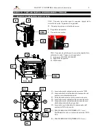
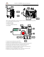
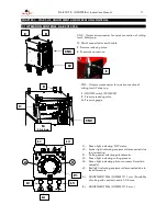
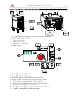
3.3 START-UP PROCESS. GAR CUT 2500/4000/5000. 

The machine must be used by as few people as possible. The equipment must never be used by untrained 

operators.   

The sequence to carry out the equipment start-up is described below: 


Connect the torch to CN3. Check it is connected properly.  


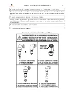
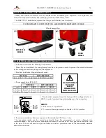
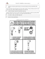
Secure the safety cap of the torch. (The coupling of the security system can be seen in the appendices).  


Connect the earth cable to W and place it in the cutting piece.  The electrical connection must be perfect. 


Place the ON/OFF switch in “ON” position.  Light L1 comes on. 


Check that the red (L2) and amber (L3) lights are not on. 


Determine suitable cutting power through P1. 


Lightly press the torch pushbutton. Air will start to flow. 


Check that the pressure gauge M mark 5.5-6 bar. There must be airflow. 


Press the torch pushbutton. Formation of arc. Light L4 comes on. 


The pilot arc which has formed is timed at 2 sec. In the event that the cutting operation is not started the 
arc will automatically go out. 


Begin to cut. Light L5 comes on. 


3.4 CUTTING PROCESS. GENERAL RECOMMENDATIONS. 


Before proceeding to carry out the cut, the correct cutting intensity must be determined depending on the 
work to be carried out. 


When  inserting  a  new  electrode  in  the  cutting  torch  proceed  to  brush  it  to  eliminate  possible  surface 
insulating layers. 


When  using  nozzle  and  long  electrodes,  for  security  reasons,  shield  cup  Ref.  51957/G  should  be 
incorporated. 


Form  the  pilot  arc  outside  the  part.  Before  forming  the  arc  we  recommend  pressing  the  pushbutton 
slightly  in  order  to  have  a  prior  airflow.  The  pilot  arc  goes  out  automatically  after  two  seconds  if  no 
cutting is done. 


If,  after  quite  a  long  cutting  process,  we  see  that  the  cutting  torch  is  heating  up,  we  advise  letting  the 
post-flow of air cool down the torch. 


Determine the correct cutting speed. The penetration as well as the cutting flash depend directly on the 
speed  used  in  the  process.  The  correct  speed  is  considered  to  be  that  which  causes  a  maximum 
inclination of the arc projected of 7 to 15º with respect to the perpendicular of the part.  


Do not touch the cutting part with the nozzle. Keep a minimum distance of 5 mm.  Use an cutting guide 
shoe. 


"Polish the electrode" 

Carry out this operation whenever there are problems in igniting the arc.


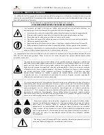
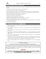
Any elements, accessory or instrument which is added to the equipment must maintain the 

basic  safety  conditions  of  the  equipment.  All  added  equipment  will  comply  with  the 
Standards and Regulations in force. 

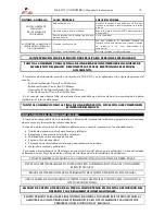
WARNING ! 

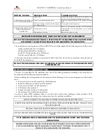
IF THE FRONT SAFETY PROTECTION OF THE TORCH HAS NOT BEEN INSERTED, 

THE MACHINE WILL NOT BE OPERATIVE.


Содержание GAR CUT 2500

Страница 1: ...f 454 00 000 GAR CUT 4000 230 400V 50 60Hz Ref 456 00 000 GAR CUT 5000 230 400V 50 60Hz Ref 456 84 000 E ESTE EQUIPO DEBE SER UTILIZADO POR PROFESIONALES EN BENEFICIO DE SU TRABAJO LEA ATENTAMENTE ESTE MANUAL GB THIS EQUIPMENT MUST BE USED BY PROFESSIONALS TO HELP YOU IN YOUR WORK CAREFULLY READ THIS MANUAL Jaime Ferrán 19 50014 ZARAGOZA Spain TLF 34 976473410 FAX 34 976472450 Ref 455 17 147 Ed 4 ...

Страница 2: ... Nº de piezas descripción y referencia de las mismas EJEMPLO GAR CUT 2500 Ref 454 00 000 230 400V 50 60Hz 1 U RUEDA FIJA Ref 455 16 032 GB CONTENTS CHAPTER 1 GENERAL DESCRIPTION TECHNICAL CHARACTERISTICS Page 15 CHAPTER 2 TRANSPORT AND INSTALLATION Page 16 CHAPTER 3 START UP ADJUSTMENT AND OPERATION CONTROLS Page 17 CHAPTER 4 MAINTENANCE OPERATIONS RECOMMENDATIONS Page 22 CHAPTER 5 ANOMALIES PROBA...

Страница 3: ...ntorcha de corte P 150 sistema de seguridad CE gafas de protección y cable de masa de conexión Para la utilización de cualquier otro accesorio consulte con el fabricante Estos equipos disponen de protección contra sobrecalentamientos falta de presión en el circuito neumático sobrecargas en el circuito de control contactos con tensiones peligrosas durante la sustitución de componentes de la cabeza ...

Страница 4: ...UT 4000 5000 40 A 230V 25 A 400V 63 A 230V 40 A 400V Manguera de alimentación RVK 1KV CUT 2500 CUT 4000 5000 Longitud 230 V 400 V 230 V 400 V 10 m 6 mm2 6 mm2 10 mm2 10 mm2 15 20 m 10 mm2 6 mm2 16 mm2 10 mm2 Los equipos standard salen de fábrica con el selector de tensión a 400 V con el fin de proteger a los mismos frente a descuidos en la conexión 230 V 1º Colocar el tornillo T en la posición 2 2...

Страница 5: ...rruptor ON OFF 230 400V R Regulador de presión M Manómetro L1 Lamparita verde indicadora de conexión ON L3 Lamparita ámbar indicadora de desconexión de equipo por sobrecalentamiento P1 Potenciómetro selector de la potencia de corte L5 Lamparita verde indicadora de proceso de corte L4 Lamparita verde indicadora de proceso de arco piloto temporizada dos segundos L2 Lamparita roja indicadora de desco...

Страница 6: ...adora de proceso de corte L4 Lamparita verde indicadora de proceso de arco piloto temporizada dos segundos L2 Lamparita roja indicadora de desconexión del equipo por falta de presión P1 potenciómetro selector de la corriente de corte Potencia de corte L3 Lamparita ámbar indicadora de desconexión de equipo por sobrecalentamiento A Indicación luminosa de diámetro de tobera a emplear B Indicación lum...

Страница 7: ...tar un electrodo nuevo en la antorcha de corte proceda a un cepillado que elimine posibles capas aislantes superficiales Utilizando tobera y electrodos largos debe incorporarse por motivos de seguridad la caperuza de protección Ref 51957 G Forme el arco piloto fuera de la pieza Previamente a la formación del arco oprima brevemente el pulsador con el fin de tener caudal de aire previo El arco pilot...

Страница 8: ...O O 0 sg OPRIME PULSADOR O I I I O PREFLUJO 0 3 sg 0 3 sg PULSADOR OPRIMIDO O I I I I IGNICIÓN H F 1 5 sg 1 8 sg PULSADOR OPRIMIDO O I I I O FINAL ARCO PILOTO 0 2 sg 2 sg COMIENZA A CORTAR I I I O O CORTE Tc sg 2 Tc sg FINALIZA DE PULSAR O I O O O FIN DE CORTE 0 sg 2 Tc sg I I O O O POST FLUJO 60 sg 62 Tc sg FINAL O O O O O INDICADORES LUMINOSOS DE SCP 2 EV2 Indicador de la acción de la electrovál...

Страница 9: ...A CAPERUZA DE PROTECCIÓN Y SEGURIDAD DE LA ANTORCHA LA MAQUINA NO SERÁ OPERATIVA PROTECCIÓN CONTRA SOBRECALENTAMIENTOS PROTECCIÓN TÉRMICA L3 En el momento que el transformador alcanza una temperatura elevada se activa un mecanismo de protección que impide la continuación de la operación de corte esto queda indicado mediante la lamparita ámbar L3 situada en el frontal de la máquina que quedará ilum...

Страница 10: ...iar Volumen de potencia inferior Rectificador transformador principal interruptores DESCARGUE PERIÓDICAMENTE EL AGUA CONDENSADA EN EL FILTRO REGULADOR Vigile la no existencia de líquido en el vaso del filtro F situado en la parte posterior del aparato Al desconectar la toma de aire se produce una descarga automática La descarga puede realizarse manualmente presionando la válvula existente en la pa...

Страница 11: ...tamiento de la antorcha con el consiguiente deterioro del cabezal de ésta MANTENER LIMPIA DE OCLUSIONES Y ESCORIAS LA TOBERA Limpiar la tobera periódicamente Si existen escorias en la base superficial pueden existir problemas de encendido de arco Utilizar un cepillo limpiador nunca elementos punzantes ya que puede deformar el orificio de la tobera NO CORTE CON LA ANTORCHA MUY CALIENTE CEPILLE LOS ...

Страница 12: ... perfectamente el contacto Cambiar microinterruptor de la antorcha SI BIEN LA MAQUINA SE ENCUENTRA CONECTADA Y CON EL PILOTO L1 ILUMINADO AL PULSAR NO EXISTE NINGÚN TIPO DE REACCIÓN Placa electrónica central SCP 2 averiada Sustituir placa electrónica SCP 2 Presión de aire regulada a un valor elevado Mediante el regulador de presión R disminuirla a un valor de 5 5 Bar Electrodo nuevo con capa super...

Страница 13: ...vo metálico en el interior del equipo TANTO AL COMIENZO COMO AL FINAL DE UNA REPARACIÓN SOPLE CON AIRE COMPRIMIDO EL INTERIOR DEL EQUIPO COMPATIBILIDAD ELECTROMAGNÉTICA CEM El usuario es responsable de la instalación y utilización del material de soldadura siguiendo las instrucciones de este manual y las siguientes recomendaciones Antes de instalar el material de soldadura debe tener en cuenta la ...

Страница 14: ...e suceder con aquellos materiales que incorporen algún tipo de tratamiento superficial cincado galvanizado etc Evítese en todo momento la inhalación de los humos desprendidos en el proceso Protéjase del humo y polvo metálico que pueda originarse Utilice máscaras anti humo homologadas El trabajo con estos equipos debe realizarse en locales o puestos de trabajo donde exista una adecuada renovación d...

Страница 15: ...wing are supplied with the equipment Cutting torch P 150 CE security system protection goggles and connection earth cable For use of any other accessory check with the manufacturer This equipment has protection against overheating lack of pressure in pneumatic circuit overloads in the control circuit contacts with dangerous voltages during the replacement of torch head components and protection ag...

Страница 16: ... 40 A 230V 25 A 400V 63 A 230V 40 A 400V Power supply hose RVK 1KV CUT 2500 CUT 4000 5000 Length 230 V 400 V 230 V 400 V 10 m 6 mm2 6 mm2 10 mm2 10 mm2 15 20 m 10 mm2 6 mm2 16 mm2 10 mm2 The standard equipment leave the factory with the voltage selector at 400 V in order to protect it against negligence in the connection 230 V 1º Place screw T in position 2 2º To connect the equipment place handle...

Страница 17: ...ap I1 ON OFF switch 230 400V R Pressure reducing valve M Pressure gauge L1 Green light indicating ON status L3 Amber light indicating equipment disconnected due to overheating P1 Cutting power selecting potentiometer L5 Green light indicating cutting process L4 Green light indicating pilot arc process timed two seconds L2 Red light indicating equipment disconnected due to lack of pressure A ADJUST...

Страница 18: ...ght indicating cutting process L4 Green light indicating pilot arc process timed two seconds L2 Red light indicating equipment disconnected due to lack of pressure P1 Cutting current selecting potentiometer Cutting capacity L3 Amber light indicating equipment disconnected due to overheating A Warning light indicating the nozzle diameter to use B Warning light indicating the cutting option with con...

Страница 19: ...to be carried out When inserting a new electrode in the cutting torch proceed to brush it to eliminate possible surface insulating layers When using nozzle and long electrodes for security reasons shield cup Ref 51957 G should be incorporated Form the pilot arc outside the part Before forming the arc we recommend pressing the pushbutton slightly in order to have a prior airflow The pilot arc goes ...

Страница 20: ...TIME ON SWITCH O O O O O 0 s PRESS BUTTON O I I I O PREFLOW 0 3 s 0 3 s BUTTON PRESSED O I I I I IGNITION H F 1 5 s 1 8 s BUTTON PRESSED O I I I O PILOT ARC END 0 2 s 2 s BEGINS TO CUT I I I O O CUTTING Tc s 2 Tc s STOP PRESSING O I O O O CUTTING END 0 s 2 Tc s I I O O O POST FLOW 60 s 62 Tc s END O O O O O LUMINOUS INDICATORS OF SCP 2 EV2 Indicates the action of the cutting electrovalve L5 light ...

Страница 21: ...S NOT BEEN INSERTED THE MACHINE WILL NOT BE OPERATIVE PROTECTION AGAINST OVERHEATING THERMAL PROTECTION L3 As soon as the transformer reaches a high temperature a protection mechanism is activated which prevents the cutting operation from being continued This is indicated by means of the amber light L3 situated on the front of the machine which will stay on when the torch pushbutton is pressed as ...

Страница 22: ...ors auxiliary transformer Power volume lower Rectifier main transformer switches FROM TIME TO TIME DISCHARGE THE WATER WHICH HAS CONDENSATED ON THE FILTER REGULATOR Control the non existence of liquid in the glass of filter F situated on the rear of the apparatus When the air intake is disconnected an automatic discharge takes place The discharge can be done manually by pressing the valve that exi...

Страница 23: ... causes the torch to heat up too much with the subsequent deterioration of the torch head KEEP THE NOZZLE CLEAN OF OCCLUSIONS AND SLAG Clean the nozzle from time to time If there is slag on the surface base there could be arc ignition problems Use a cleaning brush never sharp elements as the nozzle hole could be deformed DO NOT CUT WITH THE TORCH VERY HOT BRUSH THE NEW ELECTRODES Assembly sequence...

Страница 24: ...ch microswitch ALTHOUGH THE MACHINE IS CONNECTED AND WITH LIGHT C ON THERE IS NO REACTION WHEN PRESSED Main electronic plate SCP 2 faulty Replace electronic plate SCP 2 Air pressure set at a high value Decrease it to a value of 5 5 bar with pressure reducing valve R New electrode with insulating surface layer Brush electrode Polish the electrode Slag on flat part of the nozzle Clean the nozzle pro...

Страница 25: ...n the inside of the equipment BOTH AT THE BEGINNING AND END OF A REPAIR BLOW THE INSIDE OF THE EQUIPMENT WITH COMPRESSED AIR ELECTROMAGNETIC COMPATIBILITY CEM The user is responsible for the installation and use of the welding material according to the instructions in this manual and the following recommendations Before installing the welding material the presence of the following in the surroundi...

Страница 26: ...ry toxic This can also occur with those materials which have some kind of surface coating zinc plated galvanised etc Avoid inhaling the fumes given off in the process at all times Protect yourself from the fumes and metal dust which can be given off Use quality approved anti fume goggles Work with this equipment must be carried out in places or working posts where there is suitable air renewal If ...

Страница 27: ...os daños o gastos imprevistos o indirectos resultantes de un uso incorrecto no serán responsabilidad de GALA GAR GB APPENDICES ELECTRICAL DRAWINGS AND REFERENCE PART LISTS DECLARATION OF CONFORMITY EC MARKING ELECTRICAL DIAGRAMS DETAIL DRAWINGS AND REFERENCE LISTS GENERAL GUARANTEE CONDITIONS GALA GAR guarantees correct operation against all manufacturing defects of the GAR CUT 2500 GAR CUT 4000 a...

Страница 28: ...DOR 150A REF 45606008 MARCA REF REF DESCRIPCION 1 45416108 45416108 TERMICO N C 90ºC 2 45416208 45416208 TERMICO N A 50ºC 3 45416308 45416308 DISIPADOR PERFIL K49 L 200mm 4 45416408 45616418 MODULO TIRISTOR 5 45416508 45416508 PLACA ELECTRONICA FILTRO RCV ...

Страница 29: ...NA SALIDA CORTA 2 45412215 45612215 BOBINA CENTRAL 3 45412315 45612315 BOBINA SALIDA LARGA 4 49800001 49800001 CHAPA NUCLEO GALAMIG 300 5 58316016 58316016 CUÑA BOBINA 6 56603005 56603005 CUÑA BOBINAS DAVID 7 45910515 45910515 SOPORTE TRAFO CORTO 8 45910415 45910415 SOPORTE TRAFO CORTO C REFUERZO 9 45916915 45916915 AISLADOR ESPARRAGO DIAM 8MM ...

Страница 30: ...ROMECÁNICAS MANUFACTURE AND SALE OF AUTOGENOUS AND ELECTRIC WELDING APPLIANCES AND ELECTROMECHANICAL CONSTRUCTIONS CENTRAL Jaime Ferrán 19 nave 30 Apartado de Correos 5058 50080 ZARAGOZA Teléfono 976 47 34 10 Telefax 976 47 24 50 E mail comercial galagar com Internet http www galagar com ...

Отзывы: