Foreword
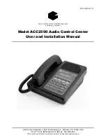
ACC2500 Audio Control Center
09/08 2
Safe Handling of CMOS Integrated Circuit Devices
Many of the integrated circuit devices used in communications equipment are of the Complementary Metal
Oxide Semiconductor (CMOS) type. Because of their high open circuit impedance, CMOS integrated
circuits are vulnerable to damage from static charges. Care must be taken handling, shipping, and
servicing them and the assemblies in which they are used.
Even though protection devices are provided in CMOS integrated circuit inputs, the protection is effective
only against over-voltage in the hundreds of volts range such as is encountered in an operating system. In a
system, circuit elements distribute static charges and load the CMOS circuits, decreasing the chance of
damage. However, CMOS circuits can be damaged by improper handling of the modules, even in a
system.
To avoid damage to circuits, observe the following handling, shipping, and servicing precautions:
1.
Prior to and while servicing a circuit module, particularly after moving within the service area,
momentarily touch both hands to a bare metal, earth-grounded surface. This will discharge any static
charge that may have accumulated on the person doing the servicing.
N
OTE
:
Wearing a conductive wrist strap will minimize static build-up during servicing.
2.
Whenever possible, avoid touching any electrically conductive parts of the circuit module with your
hands.
3.
Power down the unit before installing or removing the circuit module.
4.
When servicing a circuit module, avoid carpeted areas, dry environments, and certain types of clothing
(silk, nylon, etc.) because they contribute to static build-up. Similarly, disconnect the test probe prior
to removing the ground lead.
5.
All electrically powered test equipment should be grounded. Apply the ground lead from the test
equipment to the circuit module before connecting the test probe.
6.
If a circuit module is removed from the system, it is desirable to lay it on a conductive surface (such as
a sheet of aluminum foil) that is connected to ground through 100k of resistance.
7.
When soldering, be sure the soldering iron is grounded and has a grounded tip.
8.
Prior to connecting jumpers, replacing circuit components, or touching CMOS pins (if this becomes
necessary in the replacement of an integrated circuit device), be sure to discharge any static build-up as
described in procedure 1. Since voltage differences can exist across the human body, it is
recommended that only one hand be used if it is necessary to touch pins on the CMOS device and
associated board wiring.
9.
When replacing a CMOS integrated circuit device, leave the device in its conductive rail container or
conductive foam until it is to be inserted into the printed circuit module.
10.
All low impedance test equipment (such as pulse generators, etc.) should be connected to CMOS device
inputs after power is applied to the CMOS circuitry. Similarly, such low impedance equipment should
be disconnected before power is turned off.
11.
Replacement modules shipped separately from the factory will be packaged in a conductive material.
Any modules being transported from one area to another should be wrapped in a similar material
(aluminum foil may be used).
Never use non-conductive material
for packaging these modules.
Содержание ACC2500
Страница 43: ...39 09 08 Circuit Boards...
Страница 44: ...Circuit Boards ACC2500 Audio Control Center 40...
Страница 45: ...ACC2500 Audio Control Center Circuit Boards 41...
Страница 46: ...Circuit Boards ACC2500 Audio Control Center 42...
Страница 47: ...43 09 08 Schematics...
Страница 48: ...ACC2500 Audio Control Center Schematics 44 Desk Set Line Interface Sheet 1...
Страница 49: ...ACC2500 Audio Control Center Schematics 45 Desk Set User Audio I O Sheet 2...
Страница 50: ...Schematics ACC2500 Audio Control Center 46 Desk Set Control Microprocessor I O Sheet 3...
Страница 51: ...ACC2500 Audio Control Center Schematics 47 Desk Set DSP Block Sheet 4...
Страница 52: ...Schematics ACC2500 Audio Control Center 48 Desk Set Tone Key Panel Sheet 5...
Страница 53: ...ACC2500 Audio Control Center Schematics 49 Desk Set Power Supply Sheet 6...
Страница 54: ...Schematics ACC2500 Audio Control Center 50 Schematic Sheet 7...
Страница 55: ...ACC2500 Audio Control Center Schematics 51...
Страница 56: ...ACC2500 Audio Control Center 52 Notes...


