background image

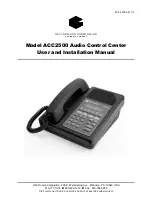
ACC2500 Audio Control Center 

Description


 5 

09/08 

Desk Set Button Panel 

TRANSMIT Button and LED

  The red 

TRANSMIT

 button is 

used to place the unit in the broadcast mode and to initiate 
voice and alarm transmissions.  The 

TRANSMIT

 LED, 

located to the left of the button, illuminates steadily when 
transmitting voice and flashes when the AMI is actively 
generating a message/alarm or in a telephone voice call. 

DEACT Button and LED

  The 

DEACT

 button is used to 

immediately deactivate all active speakers or broadcast 
assemblies and cease any activity currently on the AMI. 

VOLUME Buttons  

The units contain two buttons labeled 

VOLUME

 imprinted with up and down arrows.  They are 

used to increase and decrease the local speaker volume and 
microphone levels.  They are also used for special 
applications. 

CTL


CTL

 is used in conjunction with other buttons to 

provide secondary key functions. 

TIME

  The 

TIME

 button briefly displays the current time.  

This time is retrieved from the AMI and can be useful to 
monitor for timed events automatically generated by the AMI. 

Keypad Buttons 

 The numeric keypad is used for the selection of a desired zone and alarms.  See the 

Operations section of this manual for further information. 

STOP/CLR Button  

The 

STOP/CLR

 button serves two purposes.  While an alarm is being generated 

pressing the 

STOP/CLR

 button will stop the generation of the alarm and keep the addressed 

speakers/broadcast assemblies active for their time-out duration.  When selecting a zone or alarm, pressing 
the 

STOP/CLR

 button will, if allowed via CARD Suite, permit manual entry of the zone or alarm. 

ZONE UP and DOWN Buttons: 

The 

ZONE


UP


and


DOWN


buttons allow selection of a particular address 

or zone using preprogrammed aliases.  If no aliases have been programmed using the CARD Suite 
application, these buttons are not used. 

ALARM ON/OFF Button  

The 

ALARM


ON/OFF


button is used to turn alarm generation on or off.  When 

off, pressing the 

TRANSMIT


button will activate the selected zone and allow live voice broadcast while 

holding the 

TRANSMIT


button.  When on, the alarm will be displayed in the second line of the LCD 

display.  Pressing the 

TRANSMIT


button will initiate the alarm.  While the alarm is active, pressing the 

TRANSMIT


button will allow voice-over live broadcast while keeping the alarm playing at a reduced or 

muted level. 

ALARM UP and DOWN Buttons 

The 

ALARM


UP/DOWN


buttons allow selection of the messages as 

programmed in the AMI via the ACT tool program.


ACC2500 Front Panel 

Содержание ACC2500

Страница 1: ...Ave Mohnton PA 19540 USA 610 777 1374 800 492 1212 Fax 610 796 5954 VISIT WWW GAI TRONICS COM FOR PRODUCT LITERATURE AND MANUALS G AI T RO NI CS CO RPO RAT I O N A H U B B E L L C O M P A N Y Model AC...

Страница 2: ...t shall GAI Tronics warranty obligations with respect to services exceed 100 of the total cost of services provided hereunder Limitations Exclusions The warranty on any equipment supplied hereunder is...

Страница 3: ...ALARM 13 Handset Transmit 14 Transmit from Internal Local Microphone 14 Transmit from Desk Microphone or Footswitch 14 ALARM SELECTION 15 INITIATING ALARM BROADCASTS WITHOUT VOICE 16 STOPPING THE BROA...

Страница 4: ...AUDIO 32 MICROPHONE AUDIO 32 RELAY CONTROL MODULE 32 RESET CIRCUIT 32 CARD SUITE PROGRAMMING SOFTWARE 33 GENERAL DESCRIPTION 33 CONNECTION 33 INSTALLATION 33 READING THE UNIT 33 CARD SUITE PROGRAMMIN...

Страница 5: ...actory for repair Please call 1 800 492 1212 to obtain a Return Authorization number published repair prices and shipping instructions A Return Authorization number can also be obtained by visiting ou...

Страница 6: ...areas dry environments and certain types of clothing silk nylon etc because they contribute to static build up Similarly disconnect the test probe prior to removing the ground lead 5 All electrically...

Страница 7: ...option to be installed External Event Notification LCD indicates external Audio Messenger Interface AMI event activity such as contact closure or phone call Direct AMI Audio Monitoring User can hear...

Страница 8: ...f zones via the numeric keypad or selection of zones using a preprogrammed alias programmed using the CARD Suite software application In addition the unit allows direct entry of preprogrammed alarm me...

Страница 9: ...arms See the Operations section of this manual for further information STOP CLR Button The STOP CLR button serves two purposes While an alarm is being generated pressing the STOP CLR button will stop...

Страница 10: ...n with the CTL button Depending on its configuration the selected button illuminates when it is pressed Internal Microphone and Speaker This microphone is intended for use in low noise environments Th...

Страница 11: ...c The 5 pin power connector diagram and pinout are shown below Pin Function 1 IN 2 Battery backup IN 3 IN 4 IN 5 IN AMIConnections The rear of the ACC2500 contains two modular ports used to connect to...

Страница 12: ...un terminated Connection of these pins may damage the ACC2500 or AMI and may not be covered under warranty To facilitate the connection of these two ports to the AMI the 69612 xxx purchased separatel...

Страница 13: ...Kit XRC0001A Mounting Kit for Option Boards XAC0100A Power Supply 120 V ac 60 Hz 3308 00750 00 Power Supply 110 220 V ac 50 60 Hz 3308 00750 10 Desk Microphone XDM002A Gooseneck Microphone XGM002A Am...

Страница 14: ...I SELV powered equipment Powered by UL listed E104603 and CSA certified LR67888 Class 2 ac adapter Emissions USA FCC Part 15 Sub B Verification Canada ICES 003 Line interface FCC Part 68 Exempt Catego...

Страница 15: ...play to provide valuable operator information This information allows the operator to determine the status of the unit The following describes the display at various states At power up Initially line...

Страница 16: ...ct the desired zone This zone is displayed on the first line of the LCD display Note that during installation and programming the zone label can be changed to a desired display using the CARD Suite ap...

Страница 17: ...a second time clears the zone entry Initiating Live Voice Broadcasts without an Alarm After selecting the desired zone the operator may initiate a live broadcast immediately by pressing and holding an...

Страница 18: ...Handset Transmit Use of the handset is recommended when the desk set is located in noisy surroundings Press the handset PTT bar or TRANSMIT button and speak into the handset microphone to transmit wh...

Страница 19: ...and the last digit will become the first digit of the new alarm After entry of the alarm the display will be as shown below Z o n e Z o n e 3 A l a r m _ 1 2 The alarm aliases differ from the zone ali...

Страница 20: ...display will be as shown below AC T I V E Z o n e 3 A l a r m L o c k D o w n ACTIVE Alarm and the alarm name will be flashing indicating that the selected zone has been activated is within its time...

Страница 21: ...ONE or ALARM buttons during alarm broadcast Leaving the selected field units active will allow the selection of a new alarm without requiring the regeneration of the DTMF sequence to activate the curr...

Страница 22: ...ontrol the field units volume or to add in additional field units by specifically dialing the address of the desired field units The feature is only available while ACTIVE is flashing on the first lin...

Страница 23: ...st the local speaker volume if the handset is on hook The handset speaker volume is adjusted if the handset is off hook The display shows the new setting for two seconds after a volume change The inte...

Страница 24: ...ator to increase the sensitivity of the internal microphone when on hook or the handset microphone when off hook TRANSMIT VOL Down If the microphone sensitivity feature is enabled allows the operator...

Страница 25: ...21 09 08 Installation Planning the Installation Typical ACC2500 Connection Diagram Hot Backup ACC2500 Connection Diagram Requires the optional XRC0001A relay board and connection per Table 1 below...

Страница 26: ...ls pertaining to Class A and Class B computing devices contain warnings about possible interference with local and residential radio and TV reception Please read these warnings and all safety informat...

Страница 27: ...nuous and firmly fixed nonconductor such as porcelain tubes or flexible tubing in addition to the insulation on the wire Interconnecting cables longer than 2 meters should be rated VW 1 or FT 1 or gre...

Страница 28: ...een 1 and 5 To confirm the absolute level measure the transmit level across the TX line pair using an ac millivolt meter or dBm meter 4 After the adjustment has been made press and hold the IC button...

Страница 29: ...idetone Level Adjust Default 0 dBm PB2 DTMF Level Adjust Default 0 dBm PB3 AMI Message Diagnostic TIME Set Current Time and Date ReloadingFactory Defaults Desk sets are shipped from the factory with d...

Страница 30: ...s the PB1 button The display will indicate the current setting which is set at the factory at 10 dBm The range for this setting is variable from off to 12 dBm See the Line Output Adjustment table for...

Страница 31: ...e if the audio from the AMI is 0 dBm and the audio line has 10 dB of line loss the line input sensitivity should be set to level 4 9 dBm to accommodate the 10 dB of incurred line loss After pressing t...

Страница 32: ...s relay 1 of the relay option board This connects the RS 232 data from the AMI directly to the primary unit When power to the primary unit is lost the RS 232 connection will be made to the backup unit...

Страница 33: ...keyboard diagnostic PB4 Tone AlarmDiagnostics This function is accessible via Main Diagnostics mode select PB4 and allows adjustment of the levels of sidetone PB1 and the DTMF tones PB2 The tone leve...

Страница 34: ...er programmer to retrieve the message number as stored in the AMI of each message alarm Upon entry into this diagnostic the message number and alarm name of the first message in the list will be displ...

Страница 35: ...ed by the DSP to keep the receive audio below the maximum level of approximately 6 dBm After the receive audio has been properly compressed it is passed to A D section of U15 where it is converted to...

Страница 36: ...crocontroller using U5 C7 Each mic audio is gain compensated by U22 so that the same level is presented to the mic gain stage consisting U12 and U22 The audio is then presented to the A D section of U...

Страница 37: ...s not compatible with Windows NT The CARD Suite Programming Application components are contained on CD ROM Please exit all other programs that are running until the installation is complete Place the...

Страница 38: ...tures not found on the ACC2500 ZoneFieldName As discussed in the operations section of this manual what is displayed for the zone field name can be changed to any 8 character alphanumeric string To ch...

Страница 39: ...tion is in 5 second increments and will require that the field units be set to the same 5 second granularity If set to 0 the ACC2500 will generate the DTMF ZONE address each time a zone is addressed N...

Страница 40: ...determine the message number For example the capcode of 123001 12301 and 1231 will all address zone 123 and broadcast message 1 ProgrammableButtons The ACC2500 includes four programmable buttons that...

Страница 41: ...perly adjusted AMI Audio is low or distorted Insure that the audio level is properly adjusted for the particular speaker Insure that the line input sensitivity is properly adjusted No or low transmit...

Страница 42: ...ing ACC2500 Audio Control Center 09 08 38 Fuse Replacement CAUTION For continued safe operation replace fuses with the same type Fuses F1 and F2 are Bussmann C515S 1 25A SB 2AG Fuse F401 is Bussmann G...

Страница 43: ...39 09 08 Circuit Boards...

Страница 44: ...Circuit Boards ACC2500 Audio Control Center 40...

Страница 45: ...ACC2500 Audio Control Center Circuit Boards 41...

Страница 46: ...Circuit Boards ACC2500 Audio Control Center 42...

Страница 47: ...43 09 08 Schematics...

Страница 48: ...ACC2500 Audio Control Center Schematics 44 Desk Set Line Interface Sheet 1...

Страница 49: ...ACC2500 Audio Control Center Schematics 45 Desk Set User Audio I O Sheet 2...

Страница 50: ...Schematics ACC2500 Audio Control Center 46 Desk Set Control Microprocessor I O Sheet 3...

Страница 51: ...ACC2500 Audio Control Center Schematics 47 Desk Set DSP Block Sheet 4...

Страница 52: ...Schematics ACC2500 Audio Control Center 48 Desk Set Tone Key Panel Sheet 5...

Страница 53: ...ACC2500 Audio Control Center Schematics 49 Desk Set Power Supply Sheet 6...

Страница 54: ...Schematics ACC2500 Audio Control Center 50 Schematic Sheet 7...

Страница 55: ...ACC2500 Audio Control Center Schematics 51...

Страница 56: ...ACC2500 Audio Control Center 52 Notes...

Отзывы: