Pub. 42004-178D
Model 263 Isolation Barrier Unit (IBU)
Page: 6 of 13
\\s_eng\gtcproddocs\standard ioms - current release\42004 instr. manuals\42004-178d.doc
03/06
Mounting
1. Remove the front panel by loosening the four front captive screws.
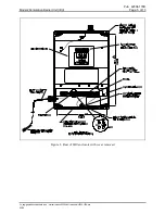
2. Refer to Figure 3. Determine which of the conduit locations is to be used. Drill spots have been
provided for use with a chassis punch or hole saw. Using a hole saw is recommended.
3. One 0.280-inch diameter hole is located in each corner of the rear enclosure. Install the rear
enclosure to a wall of an appropriate surface through the supplied mounting holes.
4. Refer to Pub. 42004-380, Control Drawing 73242, for wiring details.
N
OTE
:
Telephone system wire must be connected to the Isolation Barrier Unit only and not directly
to the I.S. telephone. Battery backup connection is not required for operation of the Model 262-001
and 272-001 I.S. Phones. If battery backup is desired, please consult the factory for specifications.
5. Apply power and test telephone operation.
6. Refer to the Troubleshooting section of problems are detected.
When proper operation has been verified, replace the cover and secure it by tightening the four captive
screws.


