AFR200 Series, Product User Guide
This document is subject to change without notice.
Caution: None of GAC products are flight certified controls including this item
Copyright © 2010, Governors America Corp., All Rights Reserved
42
PUG4144 D
speed, oil pressure, and coolant temperature information. Information regarding the Diagnostic Trouble
Codes (DTCs) is covered under the
System Diagnostics
section.
•
CANbus Termination: The AFR is not designed to be the end of line device on the CANbus. If the AFR is
located at the end of the CANbus trunk ensure that a 120
Ω
termination resistor is placed across CAN H
and CAN L (pins 18 and 19). As with all CANbus applications there needs to be a matching 120
Ω
resistor
at the other end of the trunk for a total parallel resistance of 60
Ω
.
8.3.5 Fuel Valve (Stepper Motor) Control Output
The fuel valve used by the AFR is a high-resolution bipolar stepper motor. The following table provides the
stepper motor specifications.
Stepper Motor Specification Table
Parameter
Value
Rated Operating Voltage
12V
Resistance, Inductance, Current per Phase
53Ω +/- 10%, 33.5mH, 200mA
Total Steps
240
Travel per Step
0.0164 in. [0.0417mm]
Maximum Travel
0.4 in. [10mm]
Operating Temperature
-40° to 257°F [-40° to 125°C]
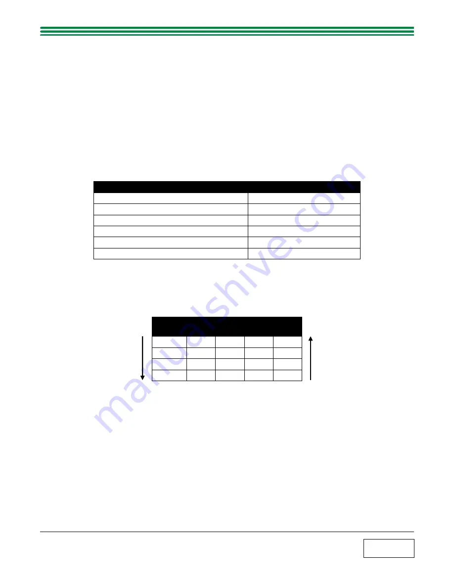
The stepper motor has two separate coils (A & B) which when provided the correct signal in the correct orientation
will modulate the stepper motor clockwise (extend) or counter-clockwise (retract). The following table details the
stepper motor input combinations for operation.
Stepper Motor Control Logic
Phase
A
Pin A
/A
Pin B
B
Pin C
/B
Pin D
1
+
-
+
-
2
+
-
-
+
3
-
+
-
+
4
-
+
+
-
Retract
Extend


