

D1033
- SIL 2 Switch / Proximity Detector Repeater Transistor Output
G.M. International ISM0043-15
9
D1033 series are isolated Intrinsically Safe Associated Apparatus installed into standard EN50022 T35 DIN Rail located in Safe Area/Non Hazardous Locations or Zone 2, Group IIC,
Temperature Classification T4, Class I, Division 2, Groups A, B, C, D, Temperature Code T4 and Class I, Zone 2, Group IIC, IIB, IIA Temperature Code T4 Hazardous Area/Hazardous
Locations (according to EN/IEC60079-15, FM Class No. 3611, CSA-C22.2 No. 213-M1987, CSA-E60079-15) within the specified operating temperature limits Tamb -20 to +60 °C,
and connected to equipment with a maximum limit for AC power supply Um of 250 Vrms.
Non-incendive field wiring is not recognized by the Canadian Electrical Code, installation is permitted in the US only.
For installation of the unit in a Class I, Division 2 or Class I, Zone 2 location, the wiring between the control equipment and the D1033 associated apparatus shall be accomplished
via conduit connections or another acceptable Division 2, Zone 2 wiring method according to the NEC and the CEC.
Not to be connected to control equipment that uses or generates more than 250 Vrms or Vdc with respect to earth ground.
D1033 series must be installed, operated and maintained only by qualified personnel, in accordance to the relevant national/international installation standards
(e.g. IEC/EN60079-14 Electrical apparatus for explosive gas atmospheres - Part 14: Electrical installations in hazardous areas (other than mines), BS 5345 Pt4, VDE 165,
ANSI/ISA RP12.06.01 Installation of Intrinsically Safe System for Hazardous (Classified) Locations, National Electrical Code NEC ANSI/NFPA 70 Section 504 and 505,
Canadian Electrical Code CEC) following the established installation rules, particular care shall be given to segregation and clear identification of I.S. conductors from non I.S. ones.
De-energize power source (turn off power supply voltage) before plug or unplug the terminal blocks when installed in Hazardous Area/Hazardous Locations or
unless area is known to be nonhazardous.
Warning: substitution of components may impair Intrinsic Safety and suitability for Division 2, Zone 2.
Explosion Hazard: to prevent ignition of flammable or combustible atmospheres, disconnect power before servicing or unless area is known to be nonhazardous.
Failure to properly installation or use of the equipment may risk to damage the unit or severe personal injury.
The unit cannot be repaired by the end user and must be returned to the manufacturer or his authorized representative. Any unauthorized modification must be avoided.
Warning
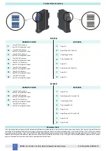
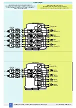
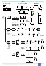
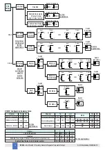
D1033 Associated Apparatus
FM Approved
under Entity Concept
and non-incendive field wiring
Unclassified Locations or
Hazardous (Classified) Locations
Class I, Division 2, Groups A, B, C, D, T-Code T4
Class I, Zone 2, Group IIC, IIB, IIA, T-Code T4
FM Approved under Entity Concept,
or third party approval
Hazardous (Classified) Locations
Class I, Division 1, Groups A, B, C, D
Class II, Division 1, Groups E, F, G
Class III, Division 1
Class I, Zone 0, Group IIC, IIB, IIA
Intrinsically
Safe Equipment
Must not use or generate
more than 250 Vrms or Vdc
Control
Equipment
Unclassified Locations
Hazardous (Classified) Locations
Class I, Division 2, Groups A, B, C, D
Class II, Division 2, Groups E, F, G
Class III, Division 2
Class I, Zone 2, Group IIC, IIB, IIA
FM Approved under non-incendive field
wiring (permitted only for US installations),
or third party approval
13
14
1
2
+
-
-
+
Power Supply
3
4
16
15
-
+
Intrinsically
Safe Equipment
Unclassified Locations or
Hazardous (Classified) Locations
Class I, Division 2, Groups A, B, C, D, T-Code T4
Class I, Zone 2, Group IIC, IIB, IIA, T-Code T4
Unclassified Locations
Must not use or generate
more than 250 Vrms or Vdc
6
5
Control
Equipment
Control
Equipment
Control
Equipment
2
6
8
7
Intrinsically
Safe Equipment
-
+
10
9
Intrinsically
Safe Equipment
+
-
11
12
+
-
Power Supply
Control
Equipment
Control
Equipment
Control
Equipment
Control
Equipment
14
9
11
12
10
16
15
13
4
3
2
7
8
6
2
6
5
1
+
-
+
+
-
-
-
+
Non-incendive
Equipment
Non-incendive
Equipment
Non-incendive
Equipment
Non-incendive
Equipment
D1033 Associated Apparatus
FM Approved
under Entity Concept
and non-incendive field wiring
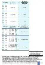
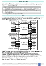
Testing procedure at T-proof
The proof test must be performed to reveal dangerous faults which cannot be otherwise detected. This means that it is necessary to specify how dangerous undetected faults, which
have been noted during the FMEDA analysis, can be revealed during the proof test.
Note for input contacts: to detect a wire break or a short circuit condition, it is necessary to mount, in the input connections and close to the contacts, a 1k
Ω
resistor in series and
a 10 k
Ω
resistor in parallel to the contacts.
The
Proof test
consists of the following steps:
This test will reveals approximately 99% of possible Dangerous Undetected failures in the repeater.
Steps
Action
1
Bypass the Safety-related PLC or take any other appropriate action to avoid a false trip.
2
Vary the state conditions of the input sensors / contacts coming from field and verify that the transistor outputs change their state from energized to
de-energized and vice-versa; also check that the de-energized state condition corresponds to the required Safety-related function.
3
Disconnect the input wiring coming from the field sensor / contact and check that the corresponding wire break alarm output is de-energized.
4
Short the input connections and verify that the corresponding outputs remains de-energized. In both cases, the corresponding alarm LEDs on the front
panel must be turned red.
5
Restore the loop to full operation.
6
Remove the bypass from the Safety-related PLC or restore normal operation.


