background image


D1033 

- SIL 2 Switch / Proximity Detector Repeater Transistor Output 

G.M. International ISM0043-15 

Must 

be 

Hazardous Area/ 

Hazardous Locations 

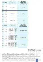
Device Parameters 

D1033 Associated 

Apparatus Parameters 

Uo / Voc = 9.6 V 

Ui / Vmax 

D1033 Terminals 

Ch1 

Ch2 

13 -14 

15 -16 

Ch3 

Ch4 

9 - 10 

11 - 12 


Io / Isc = 10 mA 

li / Imax 

Ch1 

Ch2 

13 -14 

15 -16 

Ch3 

Ch4 

9 - 10 

11 - 12 


Po / Po = 24 mW 

Pi / Pi 

Ch1 

Ch2 

13 -14 

15 -16 

Ch3 

Ch4 

9 - 10 

11 - 12 


Must 

be 

Hazardous Area/ 

Hazardous Locations 

Cable Parameters 

D1033 Terminals 

D1033 Associated 

Apparatus Parameters 

(IIC-A, B) 

(IIB-C) 

(IIA-D) 

Ci / Ci  C cable 

Ch1 

Ch2 

13 -14 

15 -16 

Ch3 

Ch4 

9 - 10 

11 - 12 


Li / Li L cable 

Ch1 

Ch2 

13 -14 

15 -16 

Ch3 

Ch4 

9 - 10 

11 - 12 


Li / Ri device and 

L cable / R cable 

Ch1 

Ch2 

13 -14 

15 -16 

Ch3 

Ch4 

9 - 10 

11 - 12 


Co / Ca = 3.5 µF 

Co / Ca = 25 µF 

(IIC-A, B) 

Lo / La = 379 mH 

Lo / La = 3000 mH 

(IIB-C) 
(IIA-D) 

Lo / La = 1500 mH 

(IIC-A, B) 

Lo / Ro = 1530 µH/


Lo / Ro = 12310 µH/


(IIB-C) 
(IIA-D) 

Lo / Ro = 6150 µH/


For installations in which both the Ci and Li of the Intrinsically Safe apparatus exceed 1 % of the Co and Lo parameters of the Associated Apparatus (excluding the cable), 
then 50 % of Co and Lo parameters are applicable and shall not be exceeded 

(50 % of the Co and Lo become the limits which must include the cable such that 

Ci C cable 

 50 % of Co and Li  L cable 

 50 % of Lo). 

If the cable parameters are unknown, the following value may be used: Capacitance 60pF per foot (180pF per meter), Inductance 0.20µH per foot (0.60µH per meter). 
The Intrinsic Safety Entity Concept allows the interconnection of Intrinsically Safe devices approved with entity parameters not specifically examined in combination as a system when 
the above conditions are respected. 
For Division 1 and Zone 0 installations, the configuration of Intrinsically Safe Equipment must be FM approved under Entity Concept (or third party approved); 
for Division 2 installations, the configuration of Intrinsically Safe Equipment must be FM approved under non-incendive field wiring or Entity Concept (or third party approved). 

NOTE for USA and Canada: 

IIC equal to Gas Groups A, B, C, D, E, F and G, 
IIB equal to Gas Groups C, D, E, F and G, 

IIA equal to Gas Groups D, E, F and G 

Co / Ca = 209 µF 

Co / Ca = 99 µF 

(I) 

Co / Ca = 25 µF 

(IIIC) 

Lo / La = 4900 mH 

(I) 

Lo / La = 1500 mH 

(IIIC) 

Lo / La = 20200 mH 

(I) 

Lo / La = 6150 mH 

(IIIC) 

Содержание D1033Q

Страница 1: ...033 SIL 2 Switch Proximity Detector Repeater Transistor Output ISM0043 15 D1033D D1033Q INSTRUCTION SAFETY MANUAL SIL 2 Switch Proximity Detector Repeater Transistor Output DIN Rail Models D1033D D103...

Страница 2: ...ms to 7113 22782 5 78 I 60079 15 T V Certificate No C IS 236198 03 SIL 2 conforms to IEC61508 2010 Ed 2 T V Certificate No C IS 236198 09 SIL 3 Functional Safety Certificate conforms to IEC61508 2010...

Страница 3: ...d in standard version D1033 Transistor Output for fault detection on dual channel version Line fault detection with common signalling available when using Power Bus enclosure Three port isolation Inpu...

Страница 4: ...Voltage free Contact Input Ch 1 for Proximity or Input Ch 1 for Voltage free Contact Input Ch 2 for Proximity Input Ch 2 for Voltage free Contact Input Ch 2 for Proximity Input Ch 2 for Voltage free C...

Страница 5: ...iated Apparatus excluding the cable then 50 of Co and Lo parameters are applicable and shall not be exceeded 50 of the Co and Lo become the limits which must include the cable such that Ci device C ca...

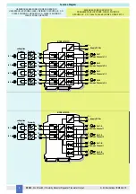
Страница 6: ...N HAZARDOUS LOCATIONS CLASS I DIVISION 2 GROUPS A B C D T Code T4 CLASS I ZONE 2 GROUP IIC T4 MODEL D1033Q 13 14 3 4 1 2 Common Channels 1 3 Supply 24 Vdc Out 1 5 6 Common Channels 2 4 Out 2 7 Out 3 8...

Страница 7: ...fety Function dd du sd su 142 61 MTBF safety function one channel 1 tot safe MTTR 8 hours 800 years no effect No Effect failures 116 69 not part Not Part failures 218 50 tot device Total Failure Rate...

Страница 8: ...rs no effect No Effect failures 127 75 not part Not Part failures 370 70 tot device Total Failure Rate Device tot safe no effect not part 645 40 MTBF device one channel 1 tot device MTTR 8 hours 176 y...

Страница 9: ...s or Hazardous Classified Locations Class I Division 2 Groups A B C D T Code T4 Class I Zone 2 Group IIC IIB IIA T Code T4 FM Approved under Entity Concept or third party approval Hazardous Classified...

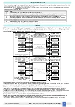
Страница 10: ...ed from each other and do not produce any unintentional connection Connect SPST output transistors checking the load rating to be within the maximum rating 100 mA 35 V resistive load The enclosure pro...

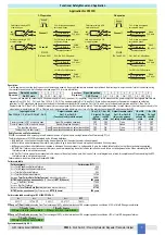
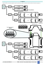
Страница 11: ...with terminating line resistor ON CH2 Setting Line fault detection ON IN OUT Operation NO NC or NC NO NO NO or NC NC ON OFF Disabled contact proximity sensor Enabled proximity sensor or contact with t...

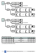
Страница 12: ...Output Input Output Output Input Output Input 9 NO 10 OR NC 9 10 9 NO 10 OR NC 9 10 7 NO 2 NC 7 2 7 NO 2 NC 7 2 Input Output Input Output Output Input Output Input 11 NO 12 OR NC 11 12 11 NO 12 OR NC...

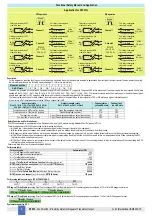
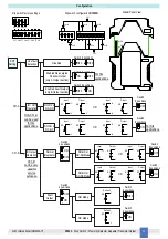
Страница 13: ...ut Input Output Output Input Output Input 13 NO 14 OR NC 13 14 13 NO 14 OR NC 13 14 1 ND 2 NE 1 2 1 ND 2 NE 1 2 ND Mode NC Mode No Fault No Fault 7 ND 2 NC 7 2 Switch 4 positions Input Output Input Ou...

Страница 14: ...utput Input Output 15 NO 16 NC 15 16 8 NC 6 NO 8 6 Switch 8 positions Input Output Input Output 15 NO 16 OR NC 15 16 8 NO 6 NC 8 6 ON Switch 8 positions OFF Switch 8 positions OR Switch 4 positions Sw...

Отзывы: