


Section 40
00-02-0893
2014-07-18
-
3 -
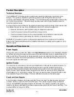
Product Description
Technical Overview
The IntelliSpark
®
16/8 series ignition systems are capacitive discharge, low-tension type
designs. The system is capable of generating precise spark timing that improves fuel
economy, load balance and ignition stability. The controller design incorporates a state-of-the-
art, 16-bit microcontroller. This technology provides users with a highly flexible solution to
meet their ignition needs.
A unique feature of this product is the patented spark plug demand voltage measurement that
is available through the use of any IntelliSpark smart coil. It allows the system to:
M
easure demand on each cylinder’s plug for diagnostic purposes.
Use the measured demand for automatic energy control.
Use the measured demand in the unique camless crank method to determine the
compression stroke, eliminating the need for a camshaft sensor.
WARNING: This system must be configured (programmed) for an engine prior to starting.
Refer to the Programming Manual for complete instructions on setting up the system to run a
specific engine.
Operational Requirements
Power Supply
The system runs on 12/24V DC. Refer to the
Specifications
section in the Installation Booklet
for details. Note that the system also requires a few seconds after power is applied before it is
able to start firing. If the system is being powered up at every start and the delay needs to be
minimal, the system can remain powered up at all times, and it will start firing coils as soon as
the crank signals are within spec.
Ignition Enable
This input can be accessed on the wiring terminal block or through the U-lead connection. To
run the engine, the Ignition Enable input should be open, and the U-lead should not be
grounded. With the Ignition Enable input shorted to the switch return, the system will shut
down, and the Tank Capacitor power supply will shut down as well so the tank voltage will
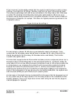
show between 0.0 v and battery voltage. The user can see the state of Ignition Enable on the
main Operator Page of the display. The tank voltmeters are also on the same page.
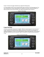
Crank and Cam Signals
Once the starter engages, the system will start firing coils when the flywheel gear teeth are
counted, and the count is found to be within spec. For 4-stroke engines using a camshaft
sensor, the CAMREF signal also needs to be detected. For camless operation, the system
needs to be able to distinguish the stroke sequence during the first four revs of test firing. The
minimum RPM for firing is 30 RPM.
Содержание IntelliSpark
Страница 1: ...00 02 0893 2014 07 18 Section 40 IgnitionSystems Operation Manual...
Страница 4: ...THIS PAGE INTENTIONALLY LEFT BLANK...
Страница 20: ......


