


Section 40
00-02-0893
2014-07-18
-
9 -
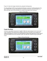
Engine View Page
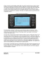
The Engine View button takes the user to a page that shows the engine block and each
cylinder. The cylinders are color coded to show the status of the kV values. Figure 7.0 shows
the 16 cylinder engine view.
In the engine block view page, the firing order is presented along the top of the page. The
RPM and timing parameters are displayed. Each cylinder is color coded green, red or yellow.
Green indicating the kV value is within normal range, yellow indicating a kV value that is
getting near the end of available kV and Red if there is a diagnostic fault associated with the
cylinder kV value.
Figure 7.0 Engine Block View
Another feature of the engine block page is the indication of the wire color of the primary lead
that should be wired to the indicated cylinder. The primary harness color code indicates what
pin it’s connected to in the primary output connector. The firing sequence on the output is
always:
Pin A, B, C, D, E, F, G, H, J, K, L, M, N, P, R, S, A, B, C…
Pin A should be wired to the first cylinder in the firing order. Pin B should be wired to the
second cylinder in the firing order and so on.
The pins are wired according to the following color code:
Pin A-Brown, B-Wht/Brn, C-Red, D-Wht/Red, E-Orange, F-Wht/Or, G-Yellow, HWht/Yel
J-Green, K-Wht/Grn, L-Blue, M-Wht/Blu, N-Vio, P-Wht/Vio, R-Gray, S-Wht/Gray
Using the firing order example shown, pin A (Brown) should go to the coil on cylinder 1L. Pin B
(Wht/Brn) goes to the coil on 1R and so on.
Содержание IntelliSpark
Страница 1: ...00 02 0893 2014 07 18 Section 40 IgnitionSystems Operation Manual...
Страница 4: ...THIS PAGE INTENTIONALLY LEFT BLANK...
Страница 20: ......


