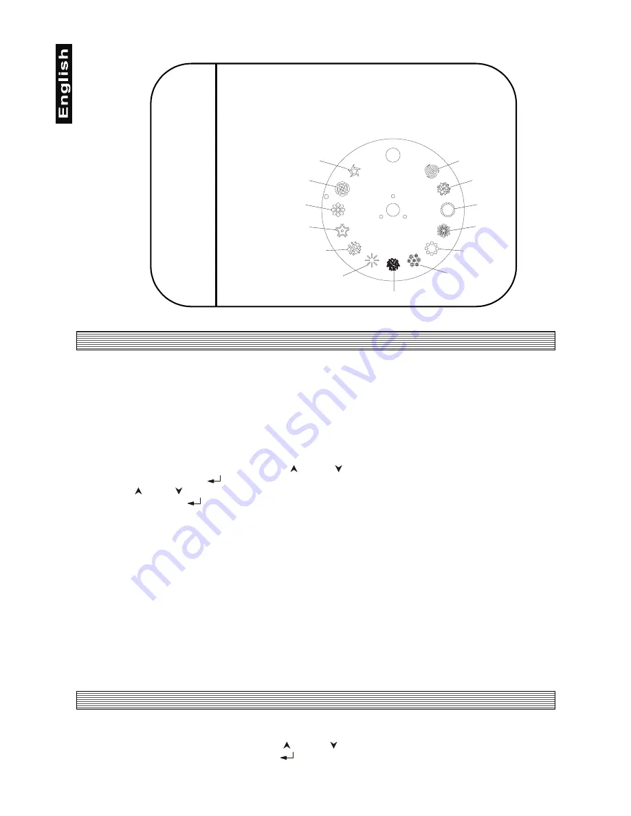
Future light sc-240 Scanner Скачать руководство пользователя страница 12

12

Gobo 1

Gobo 2

Gobo 3

Gobo 4

Gobo 5

Gobo 6

Gobo 7

Gobo 8

Gobo 9

Gobo 10

Gobo 11

Gobo 12

Gobo 13

4.1.4 Channel 4 - Shutter, Strobe, Gobos

    0 - 5

Shutter closed

    6 - 63

Full open position

  64 - 127

Strobe-effect from slow to fast (max. 8 flashes/second)

128 - 132

Closed

133 - 135

Reset of the fixture

136 - 143

Full open position

144 - 151

Closed in reverse position

152 - 159

Gobo 1

160 - 167

Gobo 2

168 - 175

Gobo 3

176 - 183

Gobo 4

184 - 191

Gobo 5

192 - 199

Gobo 6

200 - 207

Gobo 7

208 - 215

Gobo 8

216 - 223

Gobo 9

224 - 231

Gobo 10

232 - 239

Gobo 11

240 - 247

Gobo 12

248 - 255

Gobo 13

5. Addressing

The Control Board on the top side of the SC-240 allows you to assign the DMX fixture address, which is
defined as the first channel from which the SC-240 will respond to the controller.
If you set, for example, the address to channel 5, the SC-240 will use the channel 5 to 8 for control.
Please, be sure that you don’t have any overlapping channels in order to control each SC-240 correctly and
independently from any other fixture on the DMX data link.
If two, three or more SC-240 are addressed similarly, they will work similarly.

For address setting follow this procedure:

1. Switch on the SC-240 and wait until the fixture reset has finished ("rES" is flashing at the display).
2. Browse through the menu by pressing the [    ] and [    ] keys until the display shows current address
"001". Confirm by pressing 

 ] key and "001" will start to flash frequently.

3. Use the [   ] and [   ] keys to select the desired address.
4. Confirm by pressing 

 ] .

Controlling:

After having addressed all SC-240, you may now start operating these via your lighting controller.
Note:
After switching on, the SC-240 will automatically detect whether DMX 512 data is received or not. If there is
no data received at the DMX-input, the display will start to flash "001" with actually set address.
This situation can occur if:
- the 3 PIN XLR plug (cable with DMX signal from controller) is not connected with the input of the SC-240
- the controller is switched off or defective, if the cable or connector is defective or the signal wires are swap
in the input connector.

Note:
It’s necessary to insert the XLR termination plug (with 120 Ohm) in the last lighting in the link in order to
ensure proper transmission on the DMX data link.

6. Control Board

The Control Board situated on the top side of the SC-240 offers several features. You can simply set the
lighting address, run test shows, make a reset and also use special functions.
Browse through the menu by the pressing [   ] and [    ] keys - the display shows step by step these
messages: "001, rPA, rtil, tSt, rES". Press 

 ] if you wish to select one of them. The functions provided

are described in the following sections and the function hierarchy is shown below.

Содержание sc-240 Scanner

Страница 1: ...it Prohibida toda reproducci n BEDIENUNGSANLEITUNG USER MANUAL MODE D EMPLOI MANUAL DEL USUARIO 6 6FDQQHU F r weiteren Gebrauch aufbewahren Keep this manual for future needs Gardez ce mode d emploi po...

Страница 2: ...anner 51832307 FUTURELIGHT SC 740 scanner 51832317 FUTURELIGHT SC 780 scanner 51832320 FUTURELIGHT SC 940 scanner 51832323 FUTURELIGHT SC 980 scanner 51832325 FUTURELIGHT H 150 scanner 51832330 FUTURE...

Страница 3: ...Fitting Exchanging the lamp 8 3 2 Beampath 9 3 3 Rigging the fixture 9 3 4 Connection to the mains 9 3 5 DMX 512 connection connection between fixtures 10 4 DMX Protocol 11 4 1 Function of the control...

Страница 4: ...with other cables Handle the power cord and all connections with the mains with particular caution Make sure that the available voltage is not higher than stated on the rear panel Always plug in the...

Страница 5: ...opriate safety rope Only operate the fixture after having checked that the housing is firmly closed and all screws are tightly fastened The lamp must never be ignited if the objective lens or any hous...

Страница 6: ...ce 15 different dichroic colour filtres and white of which 1 is UV and 3 are bicolor filters Rainbow effect with adjustable speed in both directions Gobo wheel with 13 gobos open and blackout Strobe e...

Страница 7: ...1 Fastening screws 2 Fixation screw for bracket 3 Bracket 4 Objective 5 Mirror Rearpanel 6 DMX Output 7 DMX Input 8 Powercord 9 Fuseholder 10 Control board Control Board 11 Enter release button 12 Up...

Страница 8: ...socket Insert the lamp to the socket Do not install a lamp with a higher wattage A lamp like this generates temperatures the device is not designed for Damages caused by non observance are not subjec...

Страница 9: ...Push the lamp out by turning the screws A B C counterclockwise turn at a time the light is bright and evenly distributed 3 2 Beampath 3 3 Rigging the fixture DANGER OF FIRE When installing the device...

Страница 10: ...connect the DMX output of the controller directly with the DMX input of the first fixture in the DMX chain If you wish to connect DMX controllers with other XLR outputs you need to use adapter cables...

Страница 11: ...r can be stopped at any position you wish 4 1 3 Channel 3 Colour wheel Linear colour change following the movement of the slider In this way you can stop the colour wheel in any position also between...

Страница 12: ...owse through the menu by pressing the and keys until the display shows current address 001 Confirm by pressing key and 001 will start to flash frequently 3 Use the and keys to select the desired addre...

Страница 13: ...ust a new calibration value from range C01 C15 the wheel moves in microsteps so you can easilly center the current colour Press the display will show G08 meaning the calibration value of the gobo whee...

Страница 14: ...ns should be cleaned monthly The gobos may be cleaned with a soft brush The interior of the fixture should be cleaned at least annually using a vacuum cleaner or an air jet The dichroic colour filters...

Отзывы: