4.4.5 Relay Output Direct Drive
Figure 4.9 shows connections using the internal relay to drive a small load.
The current does not exceed 3 amperes.
3
5
4
6
or
Load
120V /240V
Mains Supply
Alarm
Output
Control
Output
Max. 3A
Resistive
Fig. 4.9 Relay Direct Drive Connections
TABLE 4.1 THERMOCOUPLE CABLE COLOUR CODES
Thermocouple
Type
Cable
Material
British
BS
American
ASTM
German
DIN
French
NFE
T
Copper
Constantan
+ white
- blue
* blue
+ blue
- red
* blue
+ red
- brown
* brown
+ yellow
- blue
* blue
J
Iron / Constantan
+ yellow
- blue
* black
+ white
- red
* black
+ red
- blue
* blue
+ yellow
- black
* black
K
Nickel Chromium
Nickel
Aluminium
+ brown
- blue
* red
+ yellow
- red
* yellow
+ red
- green
* green
+ yellow
- purple
* yellow
R
S
13% Copper
10% Copper
Nickel
+ white
- blue
* green
+ black
- red
* green
+ red
- white
* white
+ yellow
- green
* green
B
Platinum /
Rhodium
+ grey
- red
* grey
* Colour of overall sheath
11
8
+
_
0 1V, 0 5V
1 5V, 0 10V
~
~
~
~
Input Impedance = 100k ohm
11
12
+
_
0 20mA or
4 20mA
~
~
Fig. 4.7 Linear Voltage Input Connections
Fig. 4.8 Linear Current Input Connections
4.4.3 PT100 Ohm RTD Input
RTD connection are shown in Figure 4.6, with the compensating lead
connected to terminal 11. For two-wire RTD inputs, terminals 10 and 11
should be linked. The three-wire RTD offers the capability of lead resistance
compensation provided that the three leads should be of same gauge and
equal length.
4.4.4 DC Linear Input
DC linear voltage and linear current connections are shown in Figure 4.7
and Figure 4.8.
10
11
9
A
PT100
B
B
Fig. 4.6 RTD Input Connections
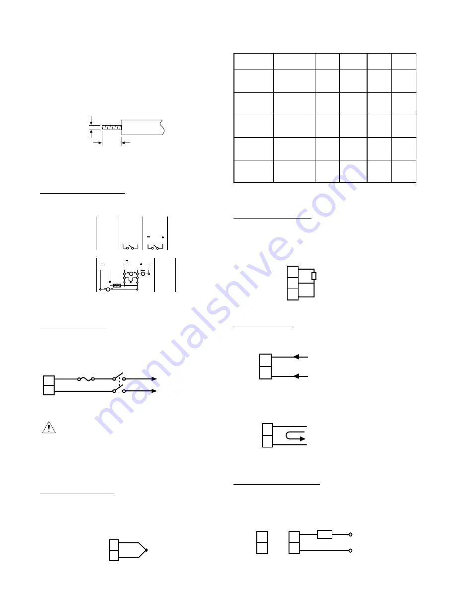
The colour codes used on the thermocouple extension leads are shown in
Table 4.1.
This equipment is designed for installation in an enclosure which
provides adequate protection against electric shock. The enclosure must
be connected to earth ground.
Local requirements regarding electrical installation should be regidly
observed. Consideration should be given to the prevention of unauthorised
personnel from gaining access to the power terminations.
4.4.2 Thermocouple Input
Thermocouple input connections are shown in Figure 4.5. The correct
type of thermocouple extension lead-wire or compensating cable must be
used for the entire distance between the controller and the thermocouple,
ensuring that the correct polarity is observed throughout. Joints in the
cable should be avoided, if possible.
Fig. 4.5 Thermocouple Input Connections
+
10
11
_
Fig. 4.4 Mains (Line) Supply Connections
* Unused control terminals should not be used as jumper points as they
may be internally connected, causing damage to the unit.
* Verify that the ratings of the output devices and the inputs as specified in
Table 4.1 on are not exceeded.
* Electric power in industrial environments contains a certain amount of
noise in the form of transient voltages and spikes. This electrical noise
can enter and adversely affect the operation of microprocessor-based
controls. For this reason we strongly recommend the use of shielded
thermocouple extension wire which connects from the sensor to the
controller. This wire is a twisted-pair construction with foil wrap and
drain wire. The drain wire is to be attached to ground at one end only.
4.4 CONNECTION AND WIRING
The following connections for outputs and inputs are provided at the rear
of the controller housing:
4.4.1 Mains (Line) Input
The controller is supplied to operate on 24V (20-32VAC/VDC) or 90-264VAC.
Check that the installation mains voltage corresponds to that indicated on
the product label before connecting power to the controllers.
+
_
RTD
0-10V
A
+
+
+
COM
_
TC
_
_
_
mV
mV
0-20 mA
4-20 mA
_
mA
B
PTA
B
_
V
POWER IN
90-264 VAC
50/60HZ
ALM OUT
3A/250 VAC
CNTL OUT
3A/250 VAC
LINEAR or
SSR DRIVE
1
2
3
4
5
6
L
N
N/O
N/O
N/O
C
C
C
8
9
10
11
12
13
14
TX1 TX2
INTERFACE
RS-485
I/O
FDC-2220
Fig. 4.3 Rear Terminal Connections
4.5
7.0 mm
0.18"
0.27"
~
~
2.0mm
0.08" max.
Fig. 4.2 Lead Termination
1
2
90 264VAC or
20 32VAC / VDC
~
~
Fuse
Page 3


