


Sensor Solution Source
Load · Torque · Pressure · Multi-Axis · Calibration · Instruments · Software
www.futek.com
IAC200 Quick Start Guide
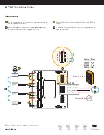
Configuration
SENSOR INPUT
CH SELECT
J5
J6
0
4
+E
–E
+S
–S
+E
–E
+S
–S
+E
–E
+S
–S
+E
–E
+S
–S
3
2
1
8
7
6
5
4
3
2
1
1
CH 1
CH 2
AMPLIFIER
(OPTIONAL)
CH 3
CH 4
SIGNAL SELECT
CH1
0 = OFF
1 = ON
CH2
CH3
CH4
Shield
Shield
DIP Switch
Selection
Span
Span
Shield
CH SELECT
0
1
CH1
CH2
CH3
CH4
B
A
A
C
Remove bottom cover of IAC200 to gain access to the
IAC200 board Connections to the IAC200 board from sensors
and IAC200 output are routed to the board through black
passthrough connections
If present, for amplified IAC200, disconnect the ribbon cable
from the center amplifier to the IAC200 board on connection J6
(Applies to FSH04736 Voltage output and FSH04737 Current
output versions )
Enable one sensor channel at a time by placing both DIP
switches to the ON position for the channel and the rest in the
OFF position As each sensor is adjusted its channel will need to
be turned on and the prior channel turned off
Set the output of the IAC200 for S (mV/V) for direct sensor
passthrough It will later be necessary to reconfigure the signal
select to V (VDC) for FSH04736 amplified voltage version and I
(mA) for FSH04737 amplified current version
B
A
C
DIP SWITCH SELECTION:
SIGNAL SELECT
1
2
3
4
5
6
7
8
▶
S (mV/V)
1
0
1
1
0
0
1
0
V (VDC)*
0
1
1
0
1
0
0
1
I (mA)*
0
1
1
0
0
1
0
1
* Use with amplifier option only