


Sensor Solution Source
Load · Torque · Pressure · Multi-Axis · Calibration · Instruments · Software
www.futek.com
3
The setup steps on the following pages involve placing a known load on
each sensor and adjusting the output down so each sensor has the same
output under the same load
The result of the setup will be a summed signal of all connected sensors
with the electrical output at the lowest sensor adjusted down to and will
reach its full electrical output change when all sensors are fully loaded
For example, four 100lbs sensors are adjusted to have the same 1 98mV/V
when100 lb is applied The final summed output will be 1 98mV/V at
400lbs, (100lbs on each sensor)
For amplified versions, voltage, or current, an extra step will be needed
to set up the amplifier using the final summed signal that will go into the
amplifier In the above example, it would mean setting up an amplifier to a
sensor with 1 98mV/V output at its fully loaded 400lb capacity
SETUP TIPS
A system calibration at FUTEK will help save time, confusion, and
potential damage by providing a plug-and-play experience with
certification Standard NIST and A2LA calibration requests are started
online at:
https://www.futek.com/recalibrationterms
Solutions are available at FUTEK to connect your IAC200 to the
computer or an instrument with a readout View FUTEK instruments at:
https://www.futek.com/store/instruments
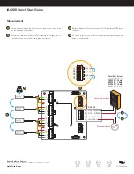
The
contains the wiring, DIP switch
locations, and power level information
IAC200 Quick Start Guide
Setup Guide
Measuring the contents of any industrial tank,
silo, or hopper requires a robust and precise
system Utilizing multiple high-capacity sensors
in conjunction with powerful instrumentation
can make for an effective platform
Sensor Solution Source
Load Cells · Pressure Sensors · Torque Sensors · Instruments · Software
APPLICATION 106
Silo Measurement
www.futek.com
A D V A N C E D S E N S O R T E C H N O L O G Y , I N C .
ISO
9001:2008
ISO
17025:2005
U.S. Manufacturer
APPLICATION SUMMARY
Measuring the contents of any industrial tank, silo, or hopper
requires a robust and precise system. Utilizing multiple high-capacity
sensors in conjunction with powerful instrumentation can make for
an effective platform.
PRODUCTS IN USE
Four Low Profile Pancake Load Cell (LCF Series) paired with
Instrumentation (IAC200 Junction Box, IPM650, IHH500, or
USB Solutions).