background image

4

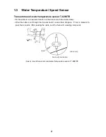
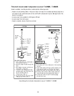
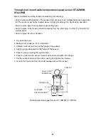
Through-hull mount water temperature/speed sensor ST-02MSB, 
ST02-PSB

Select a suitable mounting location considering the following:

• Select a mid-boat flat position. The sensor does not have to be installed perfectly perpendicu-

lar. The sensor must not be located where it might get damaged in dry-docking operation.

• Select a place apart from equipment generating heat.
• Select a place in the forward direction viewing from the drain hole, to allow for circulation of 

cooling water.

• Select a place free from vibration.

1. Dry-dock the boat.
2. Make a hole of approx. 51 mm diameter.
3. Unfasten locknut and remove the flange of the sensor.
4. Apply high-grade sealant to the flange of the sensor.
5. Pass the sensor casing through the hole.
6. Face the notch on the sensor toward boat's bow and tighten the flange.
7. Set the sensor section to the sensor casing and tighten the locknut.
8. Launch the boat and check for water leakage around the sensor.

Water temperature/speed sensor ST-02MSB, ST-02PSB

Locknut

123

Face "notch"
toward bow.

Flange nut

Coat with
silicone sealant.

51

Brim

φ

77

Содержание FCV-1150

Страница 1: ...MOUNTING 1 1 1 Display Unit 1 1 2 Transducer 1 1 3 Water Temperature Speed Sensor 2 2 WIRING 5 2 1 Interconnection 5 2 2 Wiring Standard Equipment 6 2 3 Input Output Sentences 8 3 INITIAL SETTING 10 3 1 Language Setting 10 3 2 Transducer Data 11 3 3 Speed Water Temperature Sensor Calibration 14 3 4 NMEA Port Setting 16 3 5 Heaving Setting 17 APPENDIX TRANSDUCER 82B 35R AP 1 PACKING LIST A 1 OUTLIN...

Страница 2: ......

Страница 3: ...n sink the vessel Also confirm that the transducer will not loosen by ship s vibration The installer of the equipment is solely responsible for the proper installation of the equipment FURUNO will assume no responsibility for any damage associated with improper installation ELECTRICAL SHOCK HAZARD Do not open the equipment unless totally familiar with electrical circuits and service manual Only qu...

Страница 4: ... in air The transducer may become damaged Do not install the transducer where noise or air bubbles is present Performance will be affected CAUTION The transducer cable must he handled carefully following the guidelines below Keep fuels and oils away from the cable Locate the cable where it will not be damaged The cable sheath is made of chloro phrene or polychloride vinyl which are easily by damag...

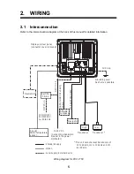
Страница 5: ...sducer Navigator Display unit CV 1150 12 24 VDC Rectifier PR 62 100 110 115 220 230 VAC 1㱢 50 60 Hz Optional supply Local supply External device Standard supply Temperature sensor T 02MSB etc Speed temp sensor ST 02MSB etc Satellite compass NavNet 3D ...

Страница 6: ...Thru hull pipe Tank Cable MJ A6SPF0003 050C 000 154 054 10 one end 6 pin 5 m for navigator CO SPEVV SBC 2Px0 2SQ LF 000 111 680 10 5 m 000 120 792 10 10 m 000 120 793 10 15 m Water temperature sensor T 02MSB 000 040 040 Thru hull type T 02MTB 000 040 026 Transom type T 03MSB 000 040 027 Thru hull type Speed Tempera ture sensor ST 02MSB 000 137 986 01 Thru hull type ST 02PSB 000 137 987 01 Thru hul...

Страница 7: ... 88 Steel 28F 18 88B 10 TFB 7000 2 T 636 FRP TRB 1100 2 T 636 F 28 200 Steel 28F 18 200B 8 8B TFB 7000 2 T 638 FRP TRB 1100 2 T 638 F Steel 28BL 6HR 200B 8 8B TFB 7000 2 T 693 FRP TRB 1100 2 T 693 F 38 200 Steel 38BL 9HR 200B 8 8B TFB 7000 2 T 693 FRP TRB 1100 2 T 693 F 50 82 Steel 50B 12 82B 35R TFB 7000 2 T 643 FRP TRB 1100 2 T 643 F 50 88 Steel 50B 12 88B 10 TFB 7000 2 T 643 FRP TRB 1100 2 T 64...

Страница 8: ... 24H 50BL 24H TFB 7000 2 T 696 FRP TRB 1100 2 T 696 F Steel 28F 24H 50BL 24HR TFB 7000 2 T 681 FRP TRB 1100 2 T 681 F Steel 28F 24H 50F 24H TFB 7000 2 T 681 FRP TRB 1100 2 T 681 F 28 88 Steel 28BL 12HR 88F 126H TFB 7000 2 T 682 FRP TRB 1100 2 T 682 F Steel 28F 24H 88F 126H TFB 7000 2 T 682 FRP TRB 1100 2 T 682 F 28 150 Steel 28BL 12HR 150B 12H TFB 7000 2 T 683 FRP TRB 1100 2 T 683 F Steel 28F 24H ...

Страница 9: ...FB 7000 2 T 683 FRP TRB 1100 2 T 683 F Steel 50F 24H 200B 12H TFB 7000 2 T 683 FRP TRB 1100 2 T 683 F 68 150 Steel 68F 30H 150B 12H TFB 7000 2 T 646 FRP TRB 1100 2 T 646 F 68 200 Steel 68F 30H 200B 12H TFB 7000 2 T 646 FRP TRB 1100 2 T 646 F 88 150 Steel 88F 126H 150B 12H TFB 7000 2 T 685 FRP TRB 1100 2 T 685 F 88 200 Steel 88F 126H 200B 12H TFB 7000 2 T 685 FRP TRB 1100 2 T 685 F 1k 28 Steel 28F ...

Страница 10: ...1 T 608 F 3k 28 Steel 28F 24H TFB 4000 1 T 616 FRP TRB 1000 1 T 616 F Steel 28BL 12HR TFB 4000 1 T 616 FRP TRB 1000 1 T 616 F 38 Steel 38BL 15HR TFB 4000 1 T 616 FRP TRB 1000 1 T 616 F 50 Steel 50F 24H TFB 4000 1 T 616 FRP TRB 1000 1 T 616 F Steel 50BL 24HR TFB 4000 1 T 616 FRP TRB 1000 1 T 616 F Steel 50BL 24H TFB 4000 1 T 694 FRP TRB 1000 1 T 694 F 68 Steel 68F 30H TFB 5000 1 T 614 FRP TRB 1000 ...

Страница 11: ...k of this manual 1 2 Transducer The performance of the echo sounder depends upon the transducer position A place least affect ed by air bubbles should be selected since turbulence blocks the sounding path Further select a place least influenced by engine noise It is known that air bubbles are fewest at the place where the bow first falls and the next wave rises at usual cruising speed Note The fac...

Страница 12: ...ation on the transom with the cable clamp When the cable is led through the transom board make a hole of approx 17 mm in diameter to pass the connector After passing the cable seal the hole with a sealing compound How to mount transom mount water temperature sensor T 02MTB D 500 D 5X20 Flush with hull bottom Units mm ...

Страница 13: ...ket Locknut Locknut Washer Gasket Holder Guide Sensor Holder T 02MSB T 03MSB Mounting procedure 1 Drill a hole of 21 mm in diameter in the mounting location 2 Pass the sensor cable through the hole 3 Pass gasket washer and locknut onto cable in that order 4 Coat the sensor flange with high quality sealant and then fasten the sensor with the locknut Torque max 59N m 5 Launch the boat to check for w...

Страница 14: ...ole to allow for circulation of cooling water Select a place free from vibration 1 Dry dock the boat 2 Make a hole of approx 51 mm diameter 3 Unfasten locknut and remove the flange of the sensor 4 Apply high grade sealant to the flange of the sensor 5 Pass the sensor casing through the hole 6 Face the notch on the sensor toward boat s bow and tighten the flange 7 Set the sensor section to the sens...

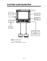
Страница 15: ... 5 Rectifier PR 62 100 110 115 220 230 VAC 1φ 50 60 Hz Option Local supply External device Standard supply Transducer This unit cannot accept transducers of 53 to 65 kHz 111 to 139 kHz and 171 to 183 kHz Satellite compass IV 2 0sq Display unit rear panel connector cover removed High MJ A6SPF0003 050C Connect to a dedicated breaker in the power distributor Grounding wire As short as possible CO SPE...

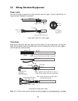
Страница 16: ...e as below Fabrication of transducer cable Note FCV 1150 cannot accept the transducers of 53 65 kHz 111 to 139 kHz and 171 183 kHz Approx 70 3 Armor Sheath Vinyl tape 6 Clamp armor with cable clamp Climp on lug FV2 M4 30 Sheath Conductor S 1 5 mm Ǟ 1 56 mm AWG16 2 DPYCY 1 5 Armor Sheath Ǟ 13 7 mm Shield Vinyl tape Sheath Wrap shield around sheath 30 mm and cut excess shield Clamp here with cable c...

Страница 17: ... series Approx 30 Shield Cut shield here and solder vinyl wire 6 Clamp vinyl sheath with cable clamp Approx 80 3 Armor Vinyl tape 6 Sheath 30 Cable connected to NMEA port Furuno cable CO SPEVV SB C 3 6 30 Cut shield here and solder vinyl wire Clamp vinyl sheath with cable clamp Vinyl tape Vinyl tape Sheath Armor Cut shield here and solder vinyl wire Clamp armor with cable clamp Cable connected to ...

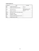
Страница 18: ...ion wind speed true or apparent RMA Latitude and longitude TD ground speed and course Loran C RMB Recommended minimum navigation information RMC Latitude and longitude speed over ground and course over ground GPS VHW True magnetic bearing speed through water VTG Speed over ground and course over ground XTE Cross track error att Roll pitch hve Heaving data req Output request for specified attribute...

Страница 19: ...ransducer and offset Ver 2 0 MTW Water temperature With connection of water temperature sensor TLL Marker line position Ver 2 0 SDmrk Mark position L L and its additional data VHW Speed thru water RMB Navigation information dat Data of specified attribute device name DBS Depth below sea surface ...

Страница 20: ...s 3 1 Language Setting 1 Press BRILL key to turn on the power The following display appears Language setting screen 2 Press T or S to select English as an example and then press the ENTER key to set The unit setting screen appears Unit setting screen 3 Set the units of measurement if necessary For example to set the distance unit press T to select Distance Unit and press the ENTER key The list of ...

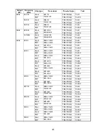
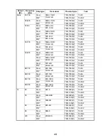
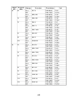
Страница 21: ...med in the FCV 1150 for ACCU FiSH Fish information display Type Output kW Tap Type Output kW Tap 28F 8 1 B 50BL 24HR 3 D 28BL 6HR 2 A 50F 24H 3 B 28F 18 2 B 68F 8H 1 A 28BL 12HR 3 A 68F 30H 3 B 28F 24H 3 D 82B 35R 2 E 38BL 9HR 2 B 88B 8 1 D 38BL 15HR 3 D 88B 10 2 C 50B 6B 1 A 88F 126H 3 E 50 200 IT 50 kHz 1 B 100B 10R 3 E 50 200 1ST 50 kHz 1 B 150B 12H 3 C 50B 9B 1 A 200B 5S 1 D 50B 12 2 A 50 200 ...

Страница 22: ...setting turn off the power then turn on the power while pressing any key Release the key after the XDCR Setting dialog box appears 1 At the transducer setting screen confirm that XDCR Select is set to XDCR Type default setting Transducer setting screen 2 If a high frequency transducer is fitted press T to select HF Connection and then press the ENTER key 3 Press S to select Connected and then pres...

Страница 23: ...2 to 8 Note Leave the Tx Power setting at Auto 10 To connect to the NavNet 3D system press T to select NavNet Mode and then press the ENTER key Select On and press the ENTER key The following program versions can be connected to the FCV 1150 MFD8 12 1950055 02 01 and later MFDBB 1950064 02 01 and later 11 Press and hold down the BRILL key to turn off the power Tap setting Set the tap according to ...

Страница 24: ...key 6 Press T or S to set the value for the frequency which is connected and then press the ENTER key 7 Press T to select Band width and then press the ENTER key 8 Press T or S to set the value for the band width and then press the ENTER key If the band width is not entered manually it is automatically set to 1 10 of the transducer frequency 9 If a low frequency transducer is fitted repeat steps 3...

Страница 25: ... example if the temperature indication is 2 5 C higher than the actual value set 2 5 C 5 To calibrate the speed value press T to select Speed STW and then press the ENTER key 6 Press T or S to set the value for the speed calibration and then press the ENTER key For example if the speed indication is 5 lower than the actual value set 5 7 To close the menu press the MENU ESC key twice ...

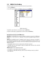
Страница 26: ...is for use with a navigator whose baud rate is 600 bps NMEA Port The NMEA terminals in the NMEA port can function as input ports or input output port Change the setting to In In when connecting GP 310B 320B and a wind sensor When con necting the GP 320B and a wind sensor first turn on WAAS Setup and then select In In as the NMEA Port setting In Out NMEA port J2 1 2 is output port and J2 3 4 is inp...

Страница 27: ...tude longitude FURUNO TLL Outputs latitude longitude depth and water temperature This requires FURUNO TLL enabled device Port Monitor Port Monitor provides information for the data sentences input from the NMEA port Press the ENTER key to display the latest data sentence information To display this information on the Port 2 screen when two sensors are connected set NMEA Port on the NMEA menu to In...

Страница 28: ...or of the satellite compass as follows TD fore aft Set the distance from antenna unit to the transducer in fore aft direction When the transducer is located on the fore side set a positive value TD port stbd Set the distance from antenna unit to the transducer in port starboard direction When the transducer is located on the starboard side set a positive value ANT TD height Set the distance from t...

Страница 29: ...side hull Code No Fasten outside hull Code No 28 82 28F 18 82B 35R Steel T 636 000 015 813 TWB 6000 2 000 015 207 TFB 7000 2 000 015 209 FRP T 636F 000 015 814 TRB 1100 2 000 015 218 50 82 50F 8G 82B 35R Steel T 636 000 015 813 TWB 6000 2 000 015 207 TFB 7000 2 000 015 209 FRP T 636F 000 015 814 TRB 1100 2 000 015 218 50B 12 82B 35R Steel T 643 000 015 821 TWB 6000 2 000 015 207 TFB 7000 2 000 015...

Страница 30: ...WR key to turn the power off and turn it on again 3 Press the MENU key to show the menu 4 Select Sounder and press the ENTER key 5 See the section 1 20 1 Sounder menu in the Operator s Manual for how to set Freq Choice and Freq Control for high and low frequencies Setting for HF connection Setting for LF connection ...

Страница 31: ... 10 トラスタッピンネジ 1シュ SELF TAPPING SCREW 5 5X20 SUS304 000 162 608 10 操作レバー TERMINAL OPENER 1 231 131 000 165 800 10 Fマウントヨウスポンジ FLUSH MOUNTING SPONGE 1 02 157 1302 0 100 342 010 10 図書 DOCUMENT 操作要領書 タゲン OPERATOR S GUIDE 1 MLG 23780 000 167 734 1 フラッシュマウント型紙 FLUSH MOUNTING TEMPLATE 1 C22 00702 ワ エイ 000 167 736 1 装備要領書 INSTALLATION MANUAL 1 IM 23780 000 167 732 1 取扱説明書 OPERATOR S MANUAL 1 OM 2378...

Страница 32: ...Oct 4 07 R Esumi ...

Страница 33: ...Oct 3 07 R Esumi ...

Страница 34: ...ON CHANGE SETTING FROM MENU 2台接続の場合 メニューにて設定変更 2 1 7 5 6 2 1 J2 TD A TD B 9 10 12V_P 12V_OV 7 SHIELD FN6 2 MJ A7SPF0013 MJ A7SPM0001 0 5m 2 無線送信機接続の場合 メニューにて設定変更 RADIO TRANSMITTER CONNECTION CHANGE SETTING FROM MENU シロ アオ WHT BLU キ ミドリ YEL GRN キ ミドリ YEL GRN シロ クロ WHT BLK TD A TD B RD A RD B NC GND ETC NAV EQUIPMENT 航法装置など 1 IV 2sq HIGH LOW 送受波器 アカ RED BLK クロ アカ RED BLK クロ TRANSDUCER 1B2 02P6350 ...

Страница 35: ......
Страница 36: ...Distributor Dealer 9 52 Ashihara cho Nishinomiya 662 8580 JAPAN Telephone 81 0 798 65 2111 Fax 81 0 798 65 4200 A DEC 2007 Printed in Japan All rights reserved D NOV 16 2011 Pub No IME 23780 D 00016773313 00016773313 REFU FCV 1150 00016773313 00016773313 0 0 0 1 6 7 7 3 3 1 3 ...

Отзывы: