iiiiiiiiiiiii
i
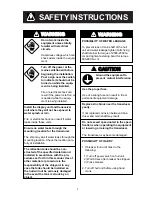
SAFETY INSTRUCTIONS
Do not work inside the
equipment unless totally
familiar with electrical
circuits.
Hazardous voltage which can
shock exists inside the equip-
ment.
Turn off the power at the
mains switchboard before
beginning the installation.
Post a sign near the switch
to indicate it should not be
turned on while the equip-
ment is being installed.
Fire or electrical shock can
result if the power is left on or
is applied while the equip-
ment is being installed.
WARNING
Install the display unit and transceiver
unit where they will not be exposed to
water splash or rain.
Fire or electrical shock can result if water
leaks inside those units.
Ensure no water leaks through the
mounting location for the transducer.
The ship may sink if water leaks through the
mounting location. Check the location care-
fully at installation.
The retraction tank should be con-
structed of the specified material and
installed in accordance with the pro-
cedures set forth in this manual. Use of
other material or procedure is the
responsibility of the shipyard. In any
case the tank should be installed so
the hull will not be seriously damaged
in the event the tank is struck by an
object.
CAUTION
Use the proper fuse.
Use of a wrong fuse can result in fire or
permanent equipment damage.
Replace zinc block near the transducer
yearly.
If not replaced corrosion between trans-
ducer and main shaft may result.
Do not exceed speed noted in the speci-
fications when operating the equipment
or lowering or raising the transducer.
The transducer may become damaged.
Ground the equipment to
prevent mutual interference.
POSSIBILITY OF INJURY
1. If breaker (hull unit) trips do the
following:
1) Turn off power swich on hull unit.
2) Wait 60 sec after breaker has tripped.
3) Press breaker.
2. Turn off hull unit before using hand
crank.
WARNING
POSSIBILITY OF WATER LEAKAGE
To prevent loss of main shaft of the hull
unit and water leakage tighten bolts fixing
shaft retainer for torque of 2000-2500 N
•
cm and tighten fastening band for torque
600-800 N
•
cm.
Содержание CSH-7
Страница 1: ...COLOR SCANNING SONAR MODEL CSH 7 ...
Страница 4: ...ii ...
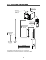
Страница 6: ...iv SYSTEM CONFIGURATION ...
Страница 15: ...1 8 ...
Страница 16: ...1 9 ...
Страница 35: ......
Страница 36: ......
Страница 37: ......
Страница 38: ......
Страница 39: ......
Страница 40: ......
Страница 41: ......
Страница 42: ......
Страница 43: ......
Страница 44: ......
Страница 45: ......
Страница 46: ......
Страница 47: ......
Страница 48: ......
Страница 49: ......
Страница 50: ......
Страница 51: ......
Страница 52: ......
Страница 53: ......
Страница 54: ......
Страница 55: ......
Страница 56: ......
Страница 57: ......
Страница 58: ......


