FFI Tech Dept. v 09.11.06 Measurements in Millimeters. 1” = 25.4mm 9 of 11
AGB Unitop
®
Model 1455-3 Door Lock
Installation Guide
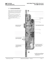
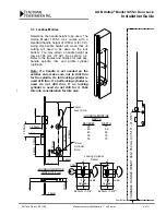
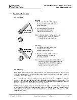
4.3 Lock Handing
The Unitop model 1455-3 lock has a reversible
self-adjusting spring latch. Before installing
lock in door lock-stile make sure you have the
correct handing. To change the handing insert
a Phillips screwdriver as shown in figure and
push in so that latch is moved out of lock body
and then twist.
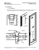
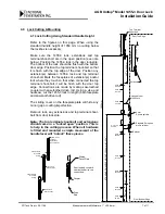
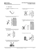
4.4 Lock Mounting
Re-insert 1455-3 lock assembly in door lock-
stile making sure the top and bottom of
assembly is flush with door edges. Make sure
sliding cover plates are moved to cover
faceplate joints. Use 3.5 x 30 mm flathead
wood screws to secure lock assembly in door
lock-stile edge.
Do not over tighten screws.
Insert lever handle and operate to make sure
shoot-bolts extend and the lock is operating
smoothly.
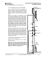
5.0 Strikes & Keeps
5.1 Thimble Keeps
After door has been properly hung in frame,
close door completely, lift up lever handle to
extend shoot-bolts enough to mark position of
shoot-bolt thimble keep. Open door. Use the
appropriate drill diameter (the thimble keeps
should have a snug press fit) and drill in head
and sill for each thimble keep. Insert thimble
keeps. Close door and check to make sure
shoot-bolts engage into thimble keeps properly.
Adjust accordingly.
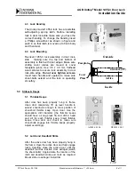
5.2 Latch and Deadbolt Strike
After the active door has been properly hung in
the frame. Open the active door and fully engage
locks. Carefully close the active door until the
deadbolt touches inactive door astragal (watch
the shoot-bolts). Approximate the location of the
latch and deadbolt strike and mark as required.
Mount strike to astragal. Install trim.
10.5
13.0
A20026.01.06
D00301.10.01
Inside
Active
Faceplate
Cover
Plate
44.4 mm (1
3
4
")
Outside
2-1/4"
1-3/4"


