background image


   FFI Tech Dept. v 09.11.06                                             Measurements in Millimeters.  1” = 25.4mm                                              7 of 11


  AGB Unitop

®

 Model 1455-3 Door Lock   

Installation Guide

4.0  Lock Cutting & Mounting 
 

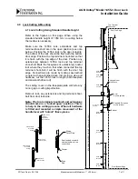
4.1 Lock Cutting Using Standard Handle Height


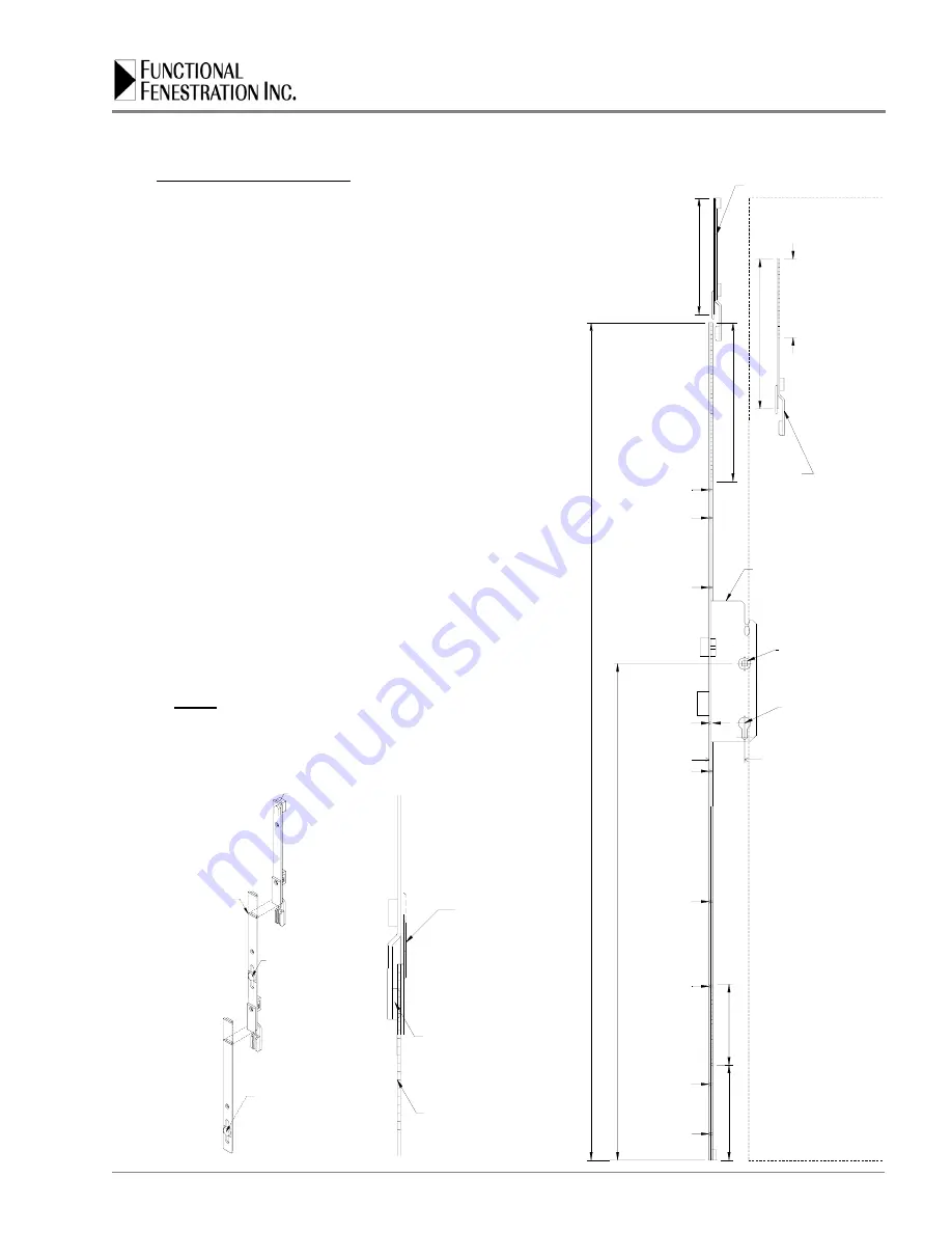
Refer to the figures on this page. When using the 
standard handle height of 1050 mm no cutting below 
the lockbox is necessary.  
 
Make sure the 1455-3 lock, extensions and top 
terminal shoot-bolt are in the open position (see note 
below). Position the 1455-3 lock in the door lock-stile. 
The bottom of the lock should be flush with the bottom 
door edge. Position the top terminal shoot-bolt so that 
it is flush with the top edge of the door. Position any 
extension(s) between 1455-3 lock and top terminal 
shoot-bolt. Mark the faceplates of extension(s) and/or 
lock where they touch so that when connected the top 
terminal shoot-bolt it will be flush with the door top 
edge. Connections are made by mating saw-toothed 
coupler with saw-toothed drive rod. Using a vise and 
hacksaw, cut the 1455-3 lock to length (both faceplate 
and saw-tooth drive rod). 
 
The sliding cover on the faceplate plate will hide any 
minor gap or cutting imperfection. 
 
Remove lock, any extensions and top terminal shoot-
bolt from door lock stile. 
 

Note: The top terminal shoot-bolt and extensions 
should come in a “locked open” position. This is 
to help in the cutting process. When all hardware 
is fitted and mounted a simple movement of the 
handle lever will “unlock” these pieces. 


1458 Lock in 

Open Position

Extension in 
Open Position

Faceplate and 

Drive Rod 

Cutting

Bottom or Top 

Terminal 
Shootbolt in 
Open Position

Faceplate and 

Drive Rod 

Cutting

Saw-toothed coupler &
saw-toothed drive rod 
connection.

Drive
Rod

Coupler

Sliding
Cover Plate

1

920 mm

CUT t

o 30

0 mm

4

00 

& 600 mm

S

T

A

N

DARD HA

NDLE

 HEI

G

HT 10

50

 mm 

(4

1-

5/

16")

Door Bottom Edge

Screw
45 mm

120

 mm

CUT -

 1

02 

mm

Screw
291.5 mm

Screw
593.5 mm

Screw
721.5 mm

Standard European
profile cylinder

8 mm
Square spindle

Screw
894 mm

P.C. Screw
939 mm

Backset

Screw

1431 mm

Screw

1182 mm

Unitop Model 
1455 Lock

Screw

1559 mm

Extension

180

 mm

CU

T

 t

o

 200

 m

m

Door Top Edge

Top Terminal 
Shootbolt

Содержание AGB Unitop 1455-3

Страница 1: ...or Lock Installation Guide Unitop Model 1455 3 Door Lock 3 Point Locking Hardware All article descriptions and technical specifications herein correspond to the time of publication FFI reserves the ri...

Страница 2: ...ristics 3 0 Door Preparation 3 1 Lock stile milling 3 2 Lockbox mortise 4 0 Lock Cutting Mounting 4 1 Lock cutting using standard handle height 4 2 Lock cutting using lowered handle height 4 3 Lock ha...

Страница 3: ...Finishes yellow bichromate silver zinc 2 0 General Description The Unitop Model 1455 3 is a multiple locking device door lock for swinging doors This door lock is designed for the securing of the acti...

Страница 4: ...FFI Tech Dept v 09 11 06 Measurements in Millimeters 1 25 4mm 4 of 11 AGB Unitop Model 1455 3 Door Lock Installation Guide 2 1 Technical Characteristics...

Страница 5: ...the lock stile A special cutter is available for the hardware groove from Functional Fenestration Inc for shaper machines Lock Stile with hardware groove Hardware Groove Lockbox Mortice in Lock Stile...

Страница 6: ...5 60 65 70 75 3 3 Lockbox Mortise Determine the handle height to be used The Unitop Model 1455 3 lock comes with a standard handle height of 1050 mm 41 34 Using this handle height will mean that no cu...

Страница 7: ...ing a vise and hacksaw cut the 1455 3 lock to length both faceplate and saw tooth drive rod The sliding cover on the faceplate plate will hide any minor gap or cutting imperfection Remove lock any ext...

Страница 8: ...sition the top terminal shoot bolt so that it is flush with the top edge of the door Position any extension s between 1455 3 lock and top terminal shoot bolt Mark the faceplates of extension s and or...

Страница 9: ...o make sure shoot bolts extend and the lock is operating smoothly 5 0 Strikes Keeps 5 1 Thimble Keeps After door has been properly hung in frame close door completely lift up lever handle to extend sh...

Страница 10: ...ed down This effectively locks the door 2 1 6 0 Operation Maintenance 6 1 Operation 6 2 Warranty Each of the Alban Giacomo spa AGB products is expressly warranted for a period of one 1 year from the d...

Страница 11: ...FFI Tech Dept v 09 11 06 Measurements in Millimeters 1 25 4mm 11 of 11 AGB Unitop Model 1455 3 Door Lock Installation Guide 6 3 Maintenance...

Отзывы: