10-9
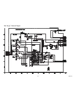
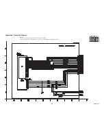
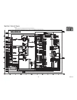
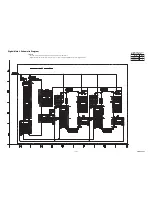
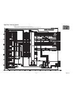
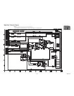
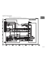
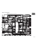
Digital Main 2 Schematic Diagram
The order of pins shown in this diagram is different from that of actual IC3301.
IC3301 is divided into six and shown as IC3301 (1/7) ~ IC3301 (7/7) in this Digital Main Schematic Diagram Section.
1 NOTE:
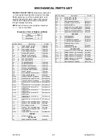
Comparison Chart of
Models and Marks
Model
Mark
LED19-T800M
A
B
LED19-H800M
A0CN6SCD2
Содержание LED19-H800M
Страница 13: ...4 2 A0CN6_N7DC 2 Rear Cabinet 1 Stand Assembly S 1 S 2 S 2 S 2 S 3 S 2 S 2 S 2 S 4 L 1 L 1 L 1 Fig D1 ...
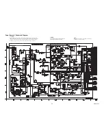
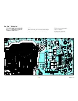
Страница 35: ...10 3 A0CN6SCP1 Power Supply 1 Schematic Diagram ...
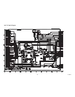
Страница 37: ...10 5 Jack 1 Schematic Diagram A0CN6SCJ1 ...
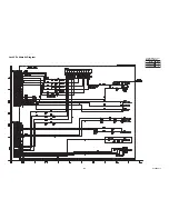
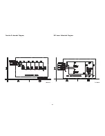
Страница 39: ...10 7 IR Sensor Schematic Diagram Function Schematic Diagram A0CN6SCF A0CN6SCIR ...
Страница 71: ...LED19 T800M LED19 H800M A0CN6EP A0CN7EP 2011 01 14 Ver 1 ...

