


M
M
D
D
2
2
2
2
7
7
8
8
H
H
i
i
g
g
h
h
P
P
e
e
r
r
f
f
o
o
r
r
m
m
a
a
n
n
c
c
e
e
M
M
i
i
c
c
r
r
o
o
s
s
t
t
e
e
p
p
p
p
i
i
n
n
g
g
D
D
r
r
i
i
v
v
e
e
r
r
V
V
1
1
.
.
0
0
10
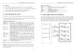
Multiple drivers:
It is recommended to have multiple drivers to share one power supply to reduce cost, provided
that the supply has enough capacity. To avoid cross interference,
DO NOT
dazy-chain the
power supply input pin of the drivers. (instead, please connect them to power supply
separately.)
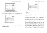
Higher supply voltage will allow higher motor speed to be achieved, at the price of more noise and
heating. If the motion speed requirement is low, it’s better to use lower supply voltage to improve
noise, heating and reliability.
NEVER connect power and ground in the wrong direction, as it will damage the driver.
6.2 Driver Voltage and Current Selection
This driver can match small and medium size step motors (NEMA 43 and 51) made by
FULLING
or other motor manufactures from around the world. To achieve good driving results, it is
important to select supply voltage and output current properly. Generally, supply voltage
determines the high speed performance of the motor, while output current determines the output
torque of the driven motor (particularly at lower speed).
●
Selecting Supply Voltage:
Higher supply voltage can increase motor torque at higher speeds, thus helpful for avoiding losing
steps. However, higher voltage may cause more motor vibration at lower speed, and it may also
cause over-voltage protection and even driver damage. Therefore, it is suggested to choose only
sufficiently high supply voltage for intended applications.
●
Setting Proper Output Current
a.
For a given motor, higher driver current will make the motor to output more torque, but at the
same time causes more heating in the motor and driver. Therefore, output current is generally
set to be such that the motor will not overheat for long time operation.
b. Since parallel and serial connections of motor coils will significantly change resulting
inductance and resistance, it is therefore important to set driver output current depending on
motor phase current, motor leads and connection methods.
c.
Phase current rating supplied by motor manufacturer is important to selecting driver current,
but the selection also depends on leads and connection.
M
M
D
D
2
2
2
2
7
7
8
8
H
H
i
i
g
g
h
h
P
P
e
e
r
r
f
f
o
o
r
r
m
m
a
a
n
n
c
c
e
e
M
M
i
i
c
c
r
r
o
o
s
s
t
t
e
e
p
p
p
p
i
i
n
n
g
g
D
D
r
r
i
i
v
v
e
e
r
r
V
V
1
1
.
.
0
0
11
7.
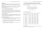
Selecting Microstep Resolution and Driver Current Output
This driver uses a 9-bit DIP switch to set microstep resolution, motor operating current and pulse
mode selection, as shown below:
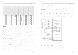
7.1 Microstep Resolution Selection
Microstep resolution is set by SW1-SW4 of the DIP switch as shown in the following table:
ustep/rev.(for 1.8
°
motor) SW1 SW2 SW3 SW4
400 ON
ON
ON
ON
500 OFF
ON
ON
ON
600 ON
OFF
ON
ON
800 OFF
OFF
ON
ON
1000 ON
ON
OFF
ON
1200
OFF ON OFF ON
1600 ON
OFF
OFF
ON
2000 OFF
OFF
OFF
ON
2400 ON
ON
ON
OFF
3200 OFF
ON
ON
OFF
4000 ON
OFF
ON
OFF
5000 OFF
OFF
ON
OFF
6000 ON
ON
OFF
OFF
6400
OFF ON OFF
OFF
8000 ON
OFF
OFF
OFF
10000 OFF
OFF
OFF
OFF
7.2 Current
Setting
The SW6-SW9 of the DIP switch are used to set the current during motion (dynamic current ).
Select a setting closest to your motor’s required current.


