


M
M
D
D
2
2
2
2
7
7
8
8
H
H
i
i
g
g
h
h
P
P
e
e
r
r
f
f
o
o
r
r
m
m
a
a
n
n
c
c
e
e
M
M
i
i
c
c
r
r
o
o
s
s
t
t
e
e
p
p
p
p
i
i
n
n
g
g
D
D
r
r
i
i
v
v
e
e
r
r
V
V
1
1
.
.
0
0
4
Extra Heat Sink
Driver’s reliable working temperature should be
<
65
℃
, motor temperature
<
80
℃
;
It is recommended automatic half-current mode, i.e. current automatically reduced by
60% when motor stops, so as to decrease driver and motor’s heating;
Please mount the driver vertically to maximize heat sink area.
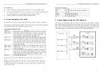
3. Driver Connectors, P1 and P2
The driver has two connectors, P1 for control signals, and P2 for power and motor connections.
The following is a brief description of the two connectors of the driver. More detailed descriptions
of the pins and related issues are presented in section 4, 5, 6, 9.
Control Signal Connector P1-pins
Signal
Functions
PUL
﹢
(+5V)
PUL- (PUL)
Pulse signal: in single pulse(pulse/direction) mode, this input represents
pulse signal, effective for each upward – rising edge; in double pulse
mode (pulse/pulse) this input represents clockwise(CW)pulse. For
reliable response, pulse width should be longer than 1.5
µ
s.
DIR+ (+5V)
DIR- (DIR)
Direction signal: in single-pulse mode, this signal has low/high voltage
levels, representing two directions of motor rotation; in double-pulse
mode (set by inside jumper JMP1), this signal is counter-clock (CCW)
pulse, effective on each rising edge. For reliable motion response,
direction signal should be sent to driver 2
µ
s before the first pulse in the
reverse motion direction.
ENA+ (+5V)
ENA- (ENA)
Enable signal: this signal is used for enable/disable, high level for
enabling driver and low level for disabling driver. Usually left
unconnected(enabled).
READY+
Output alarm signal positive: READY is a photocouper output from
open-collector circuit, effectively output when driver operate normally,
maximum permitted input voltage 30VDC; maximum output current
20mA, generally can be serial connected to PLC input terminal.
READY-
Output alarm signal negative.
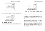
Remark 1: SW5 ON means PUL/DIR mode , OFF means CW/CCW (pulse/pulse) mode.
Remark 2: Please note motion direction is also related to motor-driver wiring match.
Exchanging the connection of two wires for a coil to the driver will reverse motion
direction. (for example, reconnecting motor A+ to driver A- and motor A- to driver A+ will
invert motion direction).
M
M
D
D
2
2
2
2
7
7
8
8
H
H
i
i
g
g
h
h
P
P
e
e
r
r
f
f
o
o
r
r
m
m
a
a
n
n
c
c
e
e
M
M
i
i
c
c
r
r
o
o
s
s
t
t
e
e
p
p
p
p
i
i
n
n
g
g
D
D
r
r
i
i
v
v
e
e
r
r
V
V
1
1
.
.
0
0
5
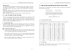
Power connector P2 pins
Signal Functions
AC
AC
AC input, varies from 80V to 220V, recommended to
use 180V.
Phase A
Motor coil A (leads A+ and A-)
Phase B
Motor coil B (leads B+ and B-)
PE
Connect ground terminal
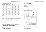
4. Control Signal Connector (P1) Interface
This driver uses differential inputs to increase noise immunity and interface flexibility.
Single-ended control signals from the indexer/controller can also be accepted by this interface. The
input circuit has built-in high-speed opto -coupler, and can accept signals in the format of line
driver, open-collector, or PNP output. Line driver (differential) signals are suggested for reliability.
In the following figures, connections to open-collector and PNP signals are illustrated.


