


M
M
D
D
2
2
2
2
7
7
8
8
H
H
i
i
g
g
h
h
P
P
e
e
r
r
f
f
o
o
r
r
m
m
a
a
n
n
c
c
e
e
M
M
i
i
c
c
r
r
o
o
s
s
t
t
e
e
p
p
p
p
i
i
n
n
g
g
D
D
r
r
i
i
v
v
e
e
r
r
V
V
1
1
.
.
0
0
6
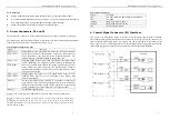
5. Driver Connection to Step Motors
MD2278 driver can drive any 4, 6, 8 lead hybrid step motors. The following diagrams illustrate
connection to various kinds of motor leads:
Figure 3: Driver Connection to Step Motor
Note that when two coils are parallelly connected, coil inductance is reduced by half and motor
speed can be significantly increased. Serial connection will lead to increased inductance and thus
the motor can be run well only at lower speeds.
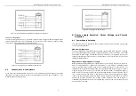
5.1
Connecting to 8-Lead Motors
8 lead motors offer a high degree of flexibility to the system designer in that they may be
connected in series or parallel, thus satisfying a wide range of applications.
Series Connection
A series motor configuration would typically be used in applications where a higher torque at
lower speeds is required. Because this configuration has the most inductance, the performance will
start to degrade at higher speeds. Use the per phase (or unipolar) current rating as the peak output
current, or multiply the bipolar current rating by 1.4 to determine the peak output current.
Figure 4: 8 Lead Motor Series Connections
M
M
D
D
2
2
2
2
7
7
8
8
H
H
i
i
g
g
h
h
P
P
e
e
r
r
f
f
o
o
r
r
m
m
a
a
n
n
c
c
e
e
M
M
i
i
c
c
r
r
o
o
s
s
t
t
e
e
p
p
p
p
i
i
n
n
g
g
D
D
r
r
i
i
v
v
e
e
r
r
V
V
1
1
.
.
0
0
7
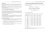
Parallel Connection
An 8 lead motor in a parallel configuration offers a more stable, but lower torque at lower speeds.
But because of the lower inductance, there will be higher torque at higher speeds. Multiply the per
phase (or unipolar) current rating by 1.96, or the bipolar current rating by 1.4, to determine the
peak output current.
Figure 5: 8 Lead Motor Parallel Connections
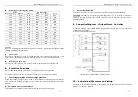
5.2
Connection to 6-Lead Motors
Like 8 lead stepping motors, 6 lead motors have two configurations available for high speed or
high torque operation. The higher speed configuration, or balf coil, is so described because it uses
one half of the motor’s inductor windings. The higher torque configuration, or full coil, use the full
windings of the phases.
Half Coil Configuration
As previously stated, the half coil configuration uses 50% of the motor phase windings. This gives
lower inductance, hence, lower torque output. Like the parallel connection of 8 lead motor, the
torque output will be more stable at higher speeds. This confi8guration is also referred to as bal
copper. In setting the driver output current multiply the specified per phase (or unipolar) current
rating by 1.4 to determine the peak output current.


