


Clear 16: Current sensor error
Hydraulic Unit LED:
Green 8 flashes / Red 4 flashes
Outdoor Unit LED:
flash
Probable causes:
•
Defective connection of electric components
•
External cause
•
Main PCB failure
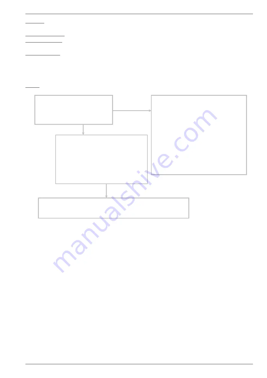
Check:
1-1 Reset power supply and operate :
1-2 Check external cause at indoor and outdoor
(voltage drop or noise) :
Does error indication show again ?
2 Check connections of outdoor unit electrical
components :
- Check if the terminal connection is loose
- Check if connector is removed
- Check erroneous connection
Upon correcting the removed connector or
mis-wiring, reset the power
3 Replace main PCB :
If checkpoints 1 and 2 do not improve the symptom, change main PCB
No
Ok
•
Instant drop
Check if there is a large load electric
apparatus in the same circuit
•
Momentary power failure
Check if there is a defective contact or leak
current in the power supply circuit
• Noise
- Check if there is any equipment causing
harmonic wave near electric line
(Neon bulb or electric equipment that
may cause harmonic wave)
- Check the complete insulation
of grounding
Yes
Maintenance document "1792 - EN"
- 19 -
Split system single phase type