background image

172

SPARC Enterprise T5120 and T5220 Servers Service Manual • July 2009

Paddle Card Overview

The paddle card serves as the interconnect between the power distribution board and
the fan power boards, hard drive backplane, and front panel I/O board.

Related Information

“Remove the Paddle Card” on page 172

Remove the Paddle Card

1. Remove the motherboard assembly.

See

“Remove the Motherboard Assembly” on page 118

.

2. Remove the power distribution board.

See

“Remove the Power Distribution Board” on page 161

.

3. Remove the fan power boards.

“Remove the Fan Power Board” on page 143

.

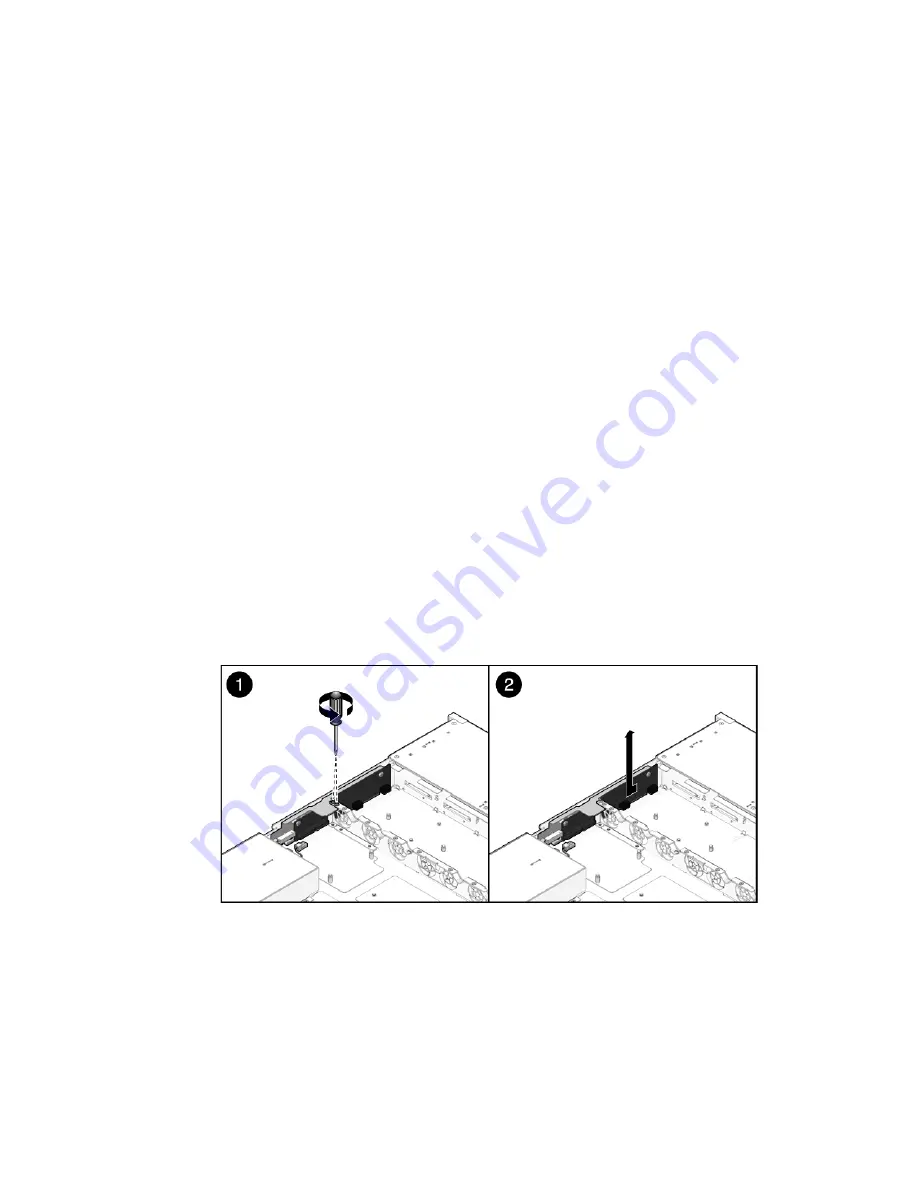
4. Remove the two No. 1 Phillips screws securing the paddle card to the chassis.

FIGURE:

Removing a Paddle Card (Illustrating Removal From a SPARC Enterprise T5120
Server)

5. Slide the paddle card back, away from its connector on the hard drive

backplane.

Содержание SPARC Enterprise T5120

Страница 1: ......

Страница 2: ......

Страница 3: ...SPARC EnterpriseTM T5120 and T5220 Servers Service Manual Part No 875 4194 13 July 2009 Revision A Manual Code C120 E463 04EN ...

Страница 4: ...demarks of Fujitsu Limited All SPARC trademarks are used under license and are registered trademarks of SPARC International Inc in the U S and other countries Products bearing SPARC trademarks are based upon architecture developed by Sun Microsystems Inc SPARC64 is a trademark of SPARC International Inc used under license by Fujitsu Microelectronics Inc and Fujitsu Limited SSH is a registered trad...

Страница 5: ...ce et sont des marques de fabrique ou des marques déposées de SPARC International Inc aux Etats Unis et dans d autres pays Les produits portant les marques SPARC sont basés sur une architecture développée par Sun Microsystems Inc SPARC64 est une marques déposée de SPARC International Inc utilisée sous le permis par Fujitsu Microelectronics Inc et Fujitsu Limited SSH est une marque déposée registre...

Страница 6: ......

Страница 7: ...0 Servers 5 Rear Panel Components and Indicators on SPARC Enterprise T5120 Servers 8 Front Panel Controls and Indicators on SPARC Enterprise T5220 Servers 9 Rear Panel Components and Indicators on SPARC Enterprise T5220 Servers 12 Status LEDs for Ethernet Ports and Network Management Port 14 Detecting and Managing Faults 15 Diagnostic Tools Overview 15 Service Processor Interfaces 16 Diagnostics T...

Страница 8: ...or Faults Detected by PSH Technology 30 Clear FRU Faults Manually 31 Display FRU Information With the show Command 32 Create an ALOM CMT Shell 32 Detecting Faults With POST 34 POST Overview 35 Managing POST Operations 35 ILOM Properties that Affect POST Behavior 35 Examples of POST Management 37 keyswitch_state Set to normal 38 keyswitch_state Set to diag 38 diag_mode Set to off 38 diag_mode Set t...

Страница 9: ...rmation 57 Safety Symbols 57 Electrostatic Discharge Safety Measures 58 Antistatic Wrist Strap Use 58 Antistatic Mat 59 Essential Tools 59 Find the Chassis Serial Number 59 Removing Power From the System 60 Power Off the Server Service Processor Command 60 Power Off the Server Power Button Graceful 62 Power Off the Server Emergency Shutdown 62 Disconnect Power Cords From the Server 62 Positioning ...

Страница 10: ...ts 81 Servicing FB DIMMs 81 Memory Fault Handling Overview 82 Identify Faulty FB DIMMs Using the show faulty Command 83 Identify Faulty FB DIMMs Using the FB DIMM Fault Locator Button 83 Remove FB DIMMs 85 Install Replacement FB DIMMs 87 Verify Successful Replacement of Faulty FB DIMMs 89 Upgrade Memory Configuration With Additional FB DIMMs 91 FB DIMM Configuration Guidelines 95 Guidelines for Up...

Страница 11: ...ttery 114 Servicing the SCC Module 114 SCC Module Overview 114 Remove a Faulty SCC Module 115 Install a New SCC Module 116 Servicing the Motherboard Assembly 117 Motherboard Servicing Overview 117 Remove the Motherboard Assembly 118 Install the Motherboard Assembly 120 Servicing Fan Modules 123 Fan Module Overview 123 Fan Module Configurations for SPARC Enterprise T5120 Servers 4 and 8 Disk Capabl...

Страница 12: ...dule 141 Servicing Fan Power Boards 143 Fan Power Board Overview 143 Remove the Fan Power Board 143 Install the Fan Power Board 145 Servicing the Hard Drive Cage 146 Hard Drive Cage Overview 146 Remove the Hard Drive Cage 146 Install the Hard Drive Cage 149 Servicing the Hard Drive Backplane 152 Hard Drive Backplane Overview 152 Remove the Hard Drive Backplane 152 Install the Hard Drive Backplane ...

Страница 13: ...on 175 Install the Top Cover 175 Reinstall the Server in the Rack 176 Return the Server to the Normal Rack Position 177 Connect Power Cords to the Server 178 Power On the Server Using the poweron Command 179 Power On the Server Using the Front Panel Power Button 180 Identifying FRUs in SPARC Enterprise T5120 Servers 181 Motherboard Components in T5120 Servers 182 I O Components in SPARC Enterprise...

Страница 14: ...n SPARC Enterprise T5220 Servers 195 Motherboard Components in T5220 Servers 196 I O Components in SPARC Enterprise T5220 Servers 198 Power Distribution Fan Module Components in SPARC Enterprise T5220 Servers 200 Internal Cables for Onboard SAS Controller Cards in SPARC Enterprise T5220 Servers 202 HDD Data Cable Routing for SAS RAID Controller Cards in SPARC Enterprise T5220 Servers 206 Index 209...

Страница 15: ...mation regarding the use and handling of this product Read this manual thoroughly Pay special attention to the section Notes on Safety on page xix Use the product according to the instructions and information available in this manual Keep this manual handy for further reference Keep this manual handy for further reference Fujitsu makes every effort to prevent users and bystanders from being injure...

Страница 16: ... install hard drives Servicing Motherboard Components on page 81 Explains how to replace the motherboard and its components Servicing Fan Modules on page 123 Explains how to service faulty fan modules Servicing Power Supplies on page 129 Explains how to remove and replace power supply modules Servicing Boards and Components on page 137 Explains how to service infrastructure boards and components R...

Страница 17: ...T5220 Server Getting Started Guide For Models That Run on DC Input Power Minimum steps to power on and boot the server that run on DC input power for the first time C120 E553 SPARC Enterprise T5120 and T5220 Servers Product Notes Information about the latest product updates and issues C120 E458 Important Safety Information for Hardware Systems Safety information that is common to all SPARC Enterpr...

Страница 18: ...ng in to ILOM 3 0 for the first time and configuring a user account or a directory service C120 E576 Integrated Lights Out Manager ILOM 3 0 Web Interface Procedures Guide Information and procedures for accessing ILOM 3 0 functions using the ILOM web interface C120 E574 Integrated Lights Out Manager ILOM 3 0 CLI Procedures Guide Information and procedures for accessing ILOM 3 0 functions using the ...

Страница 19: ...ting System documentation which is at http docs sun com Text Conventions The settings on your browser might differ from these settings Typeface Meaning Examples AaBbCc123 The names of commands files and directories on screen computer output Edit your login file Use ls a to list all files You have mail AaBbCc123 What you type when contrasted with on screen computer output su Password AaBbCc123 Book...

Страница 20: ...ry potential hazard if the user does not perform the procedure correctly Caution This indicates a hazardous situation that could result in minor or moderate personal injury if the user does not perform the procedure correctly This signal also indicates that damage to the product or other property may occur if the user does not perform the procedure correctly Caution This indicates that surfaces ar...

Страница 21: ...garding this product and the optional products provided from Fujitsu should only be performed by a certified service engineer Users must not perform these tasks Incorrect operation of these tasks may cause malfunction Also important alert messages are shown in Important Alert Messages on page xix Notes on Safety Important Alert Messages This manual provides the following important alert signals Ca...

Страница 22: ...andby power is always present in the system you must unplug the power cords before accessing any cold serviceable components The system supplies power to the power distribution board even when the server is powered off To avoid personal injury or damage to the server you must disconnect power cords before servicing the power distribution board The system supplies power to the power supply backplan...

Страница 23: ...ask Warning Maintenance Extremely hot Some components on the motherboard might be hot Use caution when handling the motherboard especially near the CPU heat sink FB DIMMs and heat sinks on the motherboard may be hot Use care when removing the bus bar screws to avoid touching a heat sink which can be dangerously hot ...

Страница 24: ...nterface cards Maintenance and inspections repairing and regular diagnosis and maintenance Caution The following tasks regarding this product and the optional products provided from Fujitsu should only be performed by a certified service engineer Users must not perform these tasks Incorrect operation of these tasks may cause malfunction Unpacking optional adapters and such packages delivered to th...

Страница 25: ...Preface xxiii Alert Label The following is a label attached to this product Never peel off the label The following label provides information to the users of this product ...

Страница 26: ...r requests regarding this document or if you find any unclear statements in the document please state your points specifically on the form at the following URL For Users in U S A Canada and Mexico https download computers us fujitsu com For Users in Other Countries http www fujitsu com global contact computing sparce_index ht ml ...

Страница 27: ...4 Internal System Cables for SPARC Enterprise T5220 Servers on page 5 Front Panel Controls and Indicators on SPARC Enterprise T5120 Servers on page 5 Rear Panel Components and Indicators on SPARC Enterprise T5120 Servers on page 8 Front Panel Controls and Indicators on SPARC Enterprise T5220 Servers on page 9 Rear Panel Components and Indicators on SPARC Enterprise T5220 Servers on page 12 Status ...

Страница 28: ...e system This board is directly connected to the paddle card and to the motherboard via a bus bar and ribbon cable This board also supports a top cover safety interlock kill switch Paddle card This board serves as the interconnect between the power distribution board and the fan power boards disk drive backplane and front I O board Fan power boards 2 These boards carry power to the system fan modu...

Страница 29: ...distributes main 12V power from the power supplies to the rest of the system This board is directly connected to the paddle card and to the motherboard via a bus bar and ribbon cable This board also supports a top cover safety interlock kill switch Power supply backplane SPARC Enterprise T5220 Servers only This board carries 12V power from the power supplies to the power distribution board over a ...

Страница 30: ...ard includes the connectors for the hard drives This board also contains the interconnect for the front I O board Power and Locator buttons and system component status LEDs Each drive has its own Power Activity Fault and Ready to Remove LEDs Front I O board This board connects directly to the hard drive backplane This board is packaged with the DVD drive as a single unit Cable Description Top cove...

Страница 31: ... the various status and fault LEDs Note The front panel also provides access to internal hard drives the removable media drive and the two front USB ports Cable Description Top cover interlock cable This cable connects the safety interlock switch on the top cover to the power distribution board Ribbon cable This cable carries signals between the power supply backplane and the power distribution bo...

Страница 32: ...FIGURE Front Panel Controls and Indicators on SPARC Enterprise T5120 Servers Figure Legend 1 Locator LED and button 5 Hard Drive map 2 Service Required LED 6 Power Supply Service Required LED 3 Power OK LED 7 Overtemp LED 4 Power button 8 Fan Module Service Required LED ...

Страница 33: ...running in its normal operating state No service actions are required Fast blink System is running in standby mode and can be quickly returned to full function Slow blink A normal but transitory activity is taking place Slow blinking might indicate that system diagnostics are running or the system is booting Power button The recessed Power button toggles the system on or off Press once to turn the...

Страница 34: ...rts PCIe ports 10 Gbit Ethernet XAUI ports if equipped and power supplies on the rear panel of SPARC Enterprise T5120 servers It also shows the locations of the rear panel LEDs FIGURE Rear Panel Components and Indicators on SPARC Enterprise T5120 Serves Figure Legend 1 PSU 0 7 Serial management port 2 PSU 1 8 Network management port 3 PCIe XAUI 0 9 Gigabit Ethernet ports 0 1 2 3 4 PCIe XAUI 1 10 U...

Страница 35: ...ILOM command set SYS LOCATE value Fast_Blink Issuing the ALOM CMT command setlocator on Pressing the Locator button Service Required LED amber If on indicates that service is required POST and ILOM are two diagnostics tools that can detect a fault or failure resulting in this indication The ILOM show faulty command provides details about any faults that cause this indicator to light Under some fau...

Страница 36: ...FIGURE Front Panel Controls and Indicators on SPARC Enterprise T5220 Servers Figure Legend 1 Locator LED and button 5 Power Supply Service Required LED 2 Service Required LED 6 Overtemp LED 3 Power OK LED 7 Fan Module Service Required LED 4 Power button 8 Hard Drive map ...

Страница 37: ... running in its normal operating state No service actions are required Fast blink System is running in standby mode and can be quickly returned to full function Slow blink A normal but transitory activity is taking place Slow blinking might indicate that system diagnostics are running or the system is booting Power button The recessed Power button toggles the system on or off Press once to turn th...

Страница 38: ...f the I O ports PCIe ports 10 Gbit Ethernet XAUI ports if equipped and power supplies on the rear panel FIGURE Rear Panel Components and Indicators on SPARC Enterprise T5220 Servers Figure Legend 1 PSU 1 8 PCIe 2 2 PSU 0 9 Rear panel status LEDs 3 PCIe 3 10 Serial management port 4 PCIe XAUI 0 11 Network management port 5 PCIe 4 12 Gigabit Ethernet ports 0 1 2 3 6 PCIe XAUI 1 13 USB ports 0 1 7 PC...

Страница 39: ...red POST and ILOM are two diagnostics tools that can detect a fault or failure resulting in this indication The ILOM show faulty command provides details about any faults that cause this indicator to light Under some fault conditions individual component fault LEDs are lit in addition to the system Service Required LED Power OK LED green Provides the following indications Off System is not running...

Страница 40: ... Amber or Green Speed indicator Amber on The link is operating as a Gigabit connection 1000 Mbps Green on The link is operating as a 100 Mbps connection Off The link is operating as a 10 Mbps connection Right LED Green Link Activity indicator Blinking A link is established Off No link is established TABLE Network Management Port LEDs NET MGT LED Color Description Left LED Green Link Activity indic...

Страница 41: ...e 53 Related Information Identifying FRUs in SPARC Enterprise T5120 Servers on page 181 Identifying FRUs in SPARC Enterprise T5220 Servers on page 195 Diagnostic Tools Overview The service processor provides a range of system management and diagnostic tools that enable you to monitor server operations and troubleshoot server problems The following is a high level summary of the various diagnostic ...

Страница 42: ...ions for repair The LEDs ILOM PSH and many of the log files and console messages are integrated For example when the Solaris software detects a fault it displays the fault logs it and passes information to ILOM where it is logged Depending on the fault one or more LEDs might also be illuminated Service Processor Interfaces There are three methods of interacting with the service processor ILOM shel...

Страница 43: ... in under one account and at the same time issue ALOM CMT shell commands while operating in another account Related Information Diagnostics Tools Quick Reference on page 17 Diagnostics Tools Quick Reference The following flowchart illustrates the complementary relationship of the different diagnostic tools and indicates a default sequence of use ...

Страница 44: ...18 SPARC Enterprise T5120 and T5220 Servers Service Manual July 2009 FIGURE Diagnostics Flowchart ...

Страница 45: ...nvironmental faults Solaris Predictive Self Healing PSH detected faults POST detected faults Faulty FRUs are identified in fault messages using the FRU name TABLE Service Related Commands on page 26 Faults Displayed by show faulty on page 29 Check the Solaris log files for fault information Flowchart item 3 The Solaris message buffer and log files record system events and provide information about...

Страница 46: ...nowledge Article web site for additional information The Knowledge Article for the fault is located at the following link http www sun com msg message ID where message ID is the value of the sunw msg id property displayed by the show faulty command After the FRU is replaced perform the procedure to clear PSH detected faults Managing Faults Using the PSH Feature on page 43 Clear PSH Detected Faults...

Страница 47: ...E System Faults and the Corresponding LED States Component Fault Fault LEDs Lit Additional Information Power supply Service Required LED front and rear panel Front panel Power Supply Fault LED Individual power supply Fault LED Power Supplies Overview on page 129 Remove a Power Supply on page 131 Install a Power Supply on page 134 Fan module Service Required LED front and rear panel Front panel Fan...

Страница 48: ...71 Install a Hard Drive on page 73 FB DIMM Service Required LED front and rear panel FB DIMM Fault LED on motherboard when FB DIMM Locate button is pressed See these sections Servicing the Motherboard Assembly on page 117 Identify Faulty FB DIMMs Using the show faulty Command on page 83 Identify Faulty FB DIMMs Using the FB DIMM Fault Locator Button on page 83 Other components Service Required LED...

Страница 49: ...s are identified in fault messages using the FRU name The service processor can detect when a fault is no longer present When this happens it clears the fault state in the FRU PROM and extinguishes the Service Required LED A fault condition can be removed in two ways Unaided recovery Faults caused by environmental conditions can clear automatically if the condition responsible for the fault improv...

Страница 50: ...lts and will not light the fault LEDs on either the chassis or the hard drive itself Use the Solaris message files to view hard drive faults For general information about ILOM see the Sun Integrated Lights Out Manager ILOM 3 0 Concepts Guide For detailed information about ILOM features that are specific to this server see the Sun Integrated Lights Out Manager ILOM 3 0 Supplement for Sun SPARC Ente...

Страница 51: ...rom the system console to the service processor How to Switch From the Service Processor to the System Console The following example showiest ILOM command for changing from the service processor to the system console If you are connected to the service processor using the ALOM CMT shell use the following command to change to the system console ok start SP console sc console ...

Страница 52: ...e dump of the Solaris OS Takes the host server from the OS to either kmdb or OpenBoot PROM equivalent to a Stop A depending on the mode Solaris software was booted set SYS component clear_fault_action true clearfault UUID Manually clears host detected faults The UUID is the unique fault ID of the fault to be cleared start SP console console f f forces the console to have read and write capabilitie...

Страница 53: ...repare_to_remove_action true removefru SYS PS0 SYS PS1 Indicates if it is okay to perform a hot swap of a power supply This command does not perform any action But this command provides a warning if the power supply should not be removed because the other power supply is not enabled reset SYS reset y c y enables you to skip the confirmation question c executes a console command after completion of...

Страница 54: ...ys static information about system FRUs defaults to all FRUs unless one is specified d displays dynamic information about system FRUs defaults to all FRUs unless one is specified See Display FRU Information With the show Command on page 32 Displays information about the FRUs in the server show SYS keyswitch_state showkeyswitch Displays the status of the virtual keyswitch show SYS LOCATE showlocato...

Страница 55: ...c System Recovery Commands on page 50 Faults Displayed by show faulty The ILOM show faulty command will display the following kinds of fault information Environmental faults Invalid configurations Faults detected during POST session Faults detected by predictive self healing PSH feature ...

Страница 56: ...how faulty Target Property Value SP faultmgmt 0 fru SYS FANBD0 FM0 SP faultmgmt 0 timestamp Dec 14 23 01 32 SP faultmgmt 0 timestamp Dec 14 23 01 32 faults 0 SP faultmgmt 0 sp_detected_fault TACH at SYS FANBD0 FM0 F0 has faults 0 exceeded low non recoverable threshold show faulty Target Property Value SP faultmgmt 0 fru SYS MB CMP0 BR1 CH0 D0 SP faultmgmt 0 timestamp Dec 14 23 01 32 SP faultmgmt 0...

Страница 57: ...ollowing a FRU replacement Note This procedure clears the fault from the service processor but not from the host If the fault persists in the host it must be manually cleared At the prompt enter the clear_fault_action property Related Info Clear PSH Detected Faults on page 47 show faulty Target Property Value SP faultmgmt 0 fru SYS MB CMP0 BR0 CH1 D0 SP faultmgmt 0 timestamp Dec 14 22 43 59 SP fau...

Страница 58: ...cessor is the ILOM shell You can use the ALOM CMT compatibility shell to emulate the ALOM CMT interface that was supported on an earlier generation of CMT servers show SYS MB CMP0 BR0 CH0 D0 SYS MB CMP0 BR0 CH0 D0 Targets R0 R1 SEEPROM SERVICE PRSNT T_AMB Properties type DIMM component_state Enabled fru_name 1024MB DDR2 SDRAM FB DIMM 333 PC2 5300 fru_description FBDIMM 1024 Mbyte fru_manufacturer ...

Страница 59: ...appear when you enter your password You can combine the create and set commands on a single line login root Password Waiting for daemons to initialize Daemons ready Integrated Lights Out Manager Version 2 0 0 0 Copyright 2007 Sun Microsystems Inc All rights reserved Use is subject to license terms Warning password is set to factory default create SP users admin Creating user Enter new password Ent...

Страница 60: ...unt using the ALOM CMT shell Related Information Diagnostics Tools Quick Reference on page 17 ILOM Troubleshooting Overview on page 23 Service Related ILOM Command Summary on page 26 Detecting Faults With POST These topics explain how to use POST as a diagnostic tool POST Overview on page 35 ILOM Properties that Affect POST Behavior on page 35 Examples of POST Management on page 37 POST Output Qui...

Страница 61: ... operations For example you can specify the events that cause POST to run the level of testing POST performs and the amount of diagnostic information POST displays You use the ILOM set command to control the state of the applicable ILOM properties These properties are listed and described in ILOM Properties that Affect POST Behavior on page 35 Related Information Managing POST Operations on page 3...

Страница 62: ...dates can be made diag_mode off POST does not run normal Runs POST according to diag_level value service Runs POST with preset values for diag_level and diag_verbosity diag_level max If diag_mode normal runs all the minimum tests plus extensive processor and memory tests min If diag_mode normal runs minimum set of tests diag_trigger none Does not run POST on reset user_reset Runs POST upon user in...

Страница 63: ...roperties Used to Manage POST Operations Examples of POST Management This topic shows examples of the ILOM set command being used to configure POST behavior The examples illustrate only a subset of the ILOM properties that can be used to control POST operations ...

Страница 64: ... virtual keyswitch property to diag diag_mode Set to off You can prevent POST from running by setting the diag_mode property to off diag_mode Set to service You force POST to run with a set of preconfigured values for diag_level and diag_verbosity by setting the diag_mode property to service Related Information ILOM Properties that Affect POST Behavior on page 35 Run POST in Maximum Mode on page 3...

Страница 65: ...te The server takes about one minute to power off 3 Switch to the system console to view the POST output The following is an partial example of POST output set SYS keyswitch_state Diag Set keyswitch_state to Diag stop SYS Are you sure you want to stop SYS y n y Stopping SYS start SYS Are you sure you want to start SYS y n y Starting SYS start SP console 2007 12 19 22 01 17 810 0 0 0 INFO STATUS Ru...

Страница 66: ...on If show faulty detects a fault the service processor logs the fault disables the faulty component and causes the Service Required LED to light In the following example FB DIMM module SYS MB CMP0 BR1 CH0 D0 is disabled 2007 12 19 22 01 32 004 0 0 0 End Neptune 1G Loopback Test Port 3 2007 12 19 22 01 32 012 0 0 0 INFO 2007 12 19 22 01 32 019 0 0 0 POST Passed all devices 2007 12 19 22 01 32 028 ...

Страница 67: ...d In this case the fault is automatically cleared from the system This procedure describes how to identify a POST detected fault and if necessary manually clear the fault 1 After replacing a faulty FRU enter the show faulty command to identify any faults detected by POST POST detected faults are distinguished by the text Forced fail No UUID number is reported for POST detected The following exampl...

Страница 68: ...he change to the component_state property to take effect 4 At the ILOM prompt use the show faulty command to verify that no faults are reported POST Output Quick Reference POST error messages use the following syntax In this syntax c the core number s the strand number Warning messages use the following syntax Informational messages use the following syntax set SYS MB CMP0 BR1 CH0 D0 component_sta...

Страница 69: ...r corrective intervention before the failure occurs Solaris PSH Feature Overview on page 44 PSH Detected Fault Console Message on page 45 Identify PSH Detected Faults With fmdump on page 45 Clear PSH Detected Faults on page 47 7 2 7 2 ERROR TEST Data Bitwalk 7 2 H W under test SYS MB CMP0 BR1 CH0 D0 7 2 Repair Instructions Replace items in order listed by H W under test above 7 2 MSG Pin 149 faile...

Страница 70: ...information about the problem from the knowledge article database The Predictive Self Healing technology covers the following server components Multicore processor Memory I O subsystem The PSH console message provides the following information about each detected fault Type Severity Description Automated response Impact Suggested action If the Solaris PSH facility detects a faulty component use th...

Страница 71: ...ifies the faulty FRU for a particular EVENT_ID UUID Note The information fmdump displays is taken from the PSH event log which retains the fault data after the fault has been repaired For that reason fmdump cannot be used to verify that a FRU replacement has cleared a fault Instead use the fmadm faulty command to verify that the fault has cleared acceptable levels Refer to http sun com msg SUN4V 8...

Страница 72: ...n about this type of fault a In a browser go to the Predictive Self Healing Knowledge Article web site http www sun com msg b Obtain the message ID from the console output or the ILOM show faulty command c Enter the message ID in the SUNW MSG ID field and click Lookup In the following example the message ID SUN4V 8000 JA provides information for corrective action fmdump v u fd940ac2 d21e c94a f258...

Страница 73: ... presence of a sunw msg id and uuid property The next step depends on whether or not a fault was reported If show faulty does not report a fault stop Do not go on to the next step If a fault is reported perform Step 3 and Step 4 Impact System performance may be affected Suggested Action for System Administrator Schedule a repair procedure to replace the affected CPU the identity of which can be de...

Страница 74: ... display OS messages from the message buffer and log files maintained by Solaris OS Check the Message Buffer on page 49 View the System Message Log Files on page 49 Check the Message Buffer 1 Log in as superuser 2 Type the dmesg command The dmesg command displays the most recent messages generated by the system View the System Message Log Files The error logging daemon syslogd automatically record...

Страница 75: ...ype the following command Managing Components With Automatic System Recovery Commands These topics explain the role played by the Automatic System Recovery ASR feature and how to manage the components it controls ASR Overview on page 50 View the System Message Log Files on page 49 Display System Components on page 51 Disable System Components on page 52 Enable System Components on page 53 ASR Over...

Страница 76: ...cores and memory are present Use the show components command to see the asrkeys on a given system After you enable or disable a component you must reset or power cycle the system for the component s change of state to take effect Related Information Display System Components on page 51 Disable System Components on page 52 Enable System Components on page 53 Display System Components The show compo...

Страница 77: ...y to Disabled 2 Reset the server so that the ASR command takes effect show components Target Property Value SYS MB RISER0 component_state Enabled PCIE0 SYS MB RISER0 component_state Disabled PCIE3 SYS MB RISER1 component_state Enabled PCIE1 SYS MB RISER1 component_state Enabled PCIE4 SYS MB RISER2 component_state Enabled PCIE2 SYS MB RISER2 component_state Enabled PCIE5 SYS MB NET0 component_state...

Страница 78: ...mponent from the ASR blacklist 1 At the prompt set the component_state property to Enabled 2 Reset the server so that the ASR command takes effect Note In the ILOM shell there is no notification when the system is actually powered off Powering off takes about a minute Use the show HOST command to determine if the host has powered off Related Information View the System Message Log Files on page 49...

Страница 79: ...dure description is based on use of the SunVTS software s browser interface which is the default interface SunVTS software also supports a TTY user interface and a command line interface CLI All three interfaces are described in the SunVTS Software User s Guide 1 Start the agent and Javabridge on the server 2 At the interface prompt choose C to start the SunVTS client 3 Start SunVTS browser enviro...

Страница 80: ...individual tests Note Use the System Exerciser High Stress Mode to test system operations Use the Component Stress High setting for the highest stress possible SunVTS Tests Field Replaceable Units Exercised by Tests Memory Test FB DIMMs Processor Test CMP motherboard Disk Test Disks cables disk backplane DVD drive Network Test Network interface network cable CMP motherboard Interconnect Test Board...

Страница 81: ... button 7 To check for SunVTS messages click on the Logs tab You can view any of the following logs Information Detailed versions of all the status and error messages that appear in the test messages area Test Error Detailed error messages from individual tests VTS Kernel vtsk Error Error messages pertaining to SunVTS software itself Look here if SunVTS software appears to be acting strangely espe...

Страница 82: ...56 SPARC Enterprise T5120 and T5220 Servers Service Manual July 2009 ...

Страница 83: ...t Follow all cautions and instructions marked on the equipment and described in the documentation shipped with your system Follow all cautions and instructions marked on the equipment and described in the SPARC Enterprise T5120 and T5220 Servers Safety and Compliance Guide Ensure that the voltage and frequency of your power source match the voltage and frequency inscribed on the equipment s electr...

Страница 84: ...sitive to static electricity Ordinary amounts of static electricity from clothing or the work environment can destroy the components located on these boards Do not touch the components along their connector edges Caution You must disconnect both power supplies before servicing any of the components documented in this chapter Antistatic Wrist Strap Use Wear an antistatic wrist strap and use an anti...

Страница 85: ...ttery removal Pen or pencil to power on server Find the Chassis Serial Number If you require technical support for your system you will be asked to provide the server s chassis serial number You can find the chassis serial number on a sticker located on the front of the server and on another sticker on the side of the server If it is not convenient to read either sticker you can run the ILOM show ...

Страница 86: ...Power Cords From the Server on page 62 Related Information Servicing the Motherboard Assembly on page 117 Servicing Boards and Components on page 137 Power Off the Server Service Processor Command You can use the service processor to perform a graceful shutdown of the server and to ensure that all of your data is saved and the server is ready for restart Properties type Host System keyswitch_state...

Страница 87: ...on these processes 4 Shut down all logical domains Refer to the Solaris system administration documentation for additional information 5 Shut down the Solaris OS Refer to the Solaris system administration documentation for additional information 6 Switch from the system console to the prompt by typing the Hash Period key sequence 7 At the prompt type the stop SYS command Note You can also use the ...

Страница 88: ...m corruption might occur Press and hold the Power button for four seconds Related Information Power Off the Server Service Processor Command on page 60 Power Off the Server Power Button Graceful on page 62 Disconnect Power Cords From the Server Unplug all power cords from the server Caution Because 3 3v standby power is always present in the system you must unplug the power cords before accessing ...

Страница 89: ...the set SYS LOCATE command from the prompt to locate the system that requires maintenance Once you have located the server press the Locator LED and button to turn it off 2 Verify that no cables will be damaged or will interfere when the server is extended Although the cable management arm CMA that is supplied with the server is hinged to accommodate extending the server you should ensure that all...

Страница 90: ...l the slide rails latch Remove the Server From the Rack The server must be removed from the rack to remove or install the following components Motherboard Power distribution board Power supply backplane SPARC Enterprise T5220 server Paddle card Disk cage Hard drive backplane Front panel light pipe assemblies Caution If necessary use two people to dismount and carry the chassis ...

Страница 91: ...nd on page 60 3 Press the metal lever that is located on the inner side of the rail to disconnect the cable management arm CMA from the rail assembly as shown in the following figure The CMA is still attached to the cabinet but the server chassis is now disconnected from the CMA FIGURE Metal Lever and Cable Management Arm Caution If necessary use two people to dismount and carry the chassis ...

Страница 92: ...wing figure A release tab is located on each rail FIGURE Release Tabs and Slide Assembly 5 Set the server on a sturdy work surface Accessing Internal Components These topics explain how to access components contained within the chassis and the steps needed to protect against damage or injury from electrostatic discharge Perform Electrostatic Discharge Prevention Measures on page 67 Remove the Top ...

Страница 93: ...cement parts or optional system components 2 Attach an antistatic wrist strap When servicing or removing server components attach an antistatic strap to your wrist and then to a metal area on the chassis Related Information General Safety Information on page 57 Remove the Top Cover 1 Unlatch the fan module door Pull the release tabs back to release the door 2 Press the top cover release button and...

Страница 94: ...8 SPARC Enterprise T5120 and T5220 Servers Service Manual July 2009 FIGURE Removing the Top Cover 3 Remove the top cover Lift up and remove the cover Related Information Install the Top Cover on page 175 ...

Страница 95: ... is running This feature referred to as being hot pluggable depends on how the hard drives are configured Note SPARC Enterprise T5120 and T5220 servers support both traditional disk based storage devices and flash SSDs diskless storage devices based on solid state memory The terms hard drive and HDD hard disk drive are used in a generic sense to refer to both types of internal storage devices To h...

Страница 96: ...our Drive Capable Backplane Configuration Reference on page 77 Eight Drive Capable Backplane Configuration Reference on page 78 Sixteen Drive Capable Backplane Configuration Reference on page 79 Hard Drive LEDs Each hard drive has a group of three status LEDs as shown in the following figure Both disk based hard drives and flash SSDs use the same set of LEDS Note The OK Activity LED has slightly d...

Страница 97: ...e chassis TABLE Status LEDs for Hard Drives LED Color Description 1 Ready to Remove Blue Indicates that a hard drive can be removed during a hot plug operation 2 Service Required Amber Indicates that the hard drive is has experienced a fault condition 3 OK Activity HDDs Green Indicates the HDD s availability for use On Drive is idle and available for use Off Read or write activity is in progress 3...

Страница 98: ... the hard drive release button to open the latch cfgadm al Ap_id Type Receptacle Occupant Condition c0 scsi bus connected configured unknown c0 dsk c1t0d0 disk connected configured unknown c0 dsk c1t1d0 disk connected configured unknown usb0 1 unknown empty unconfigured ok usb0 2 unknown empty unconfigured ok usb0 3 unknown empty unconfigured ok usb1 1 unknown empty unconfigured ok usb1 2 unknown ...

Страница 99: ...on page 73 Four Drive Capable Backplane Configuration Reference on page 77 Eight Drive Capable Backplane Configuration Reference on page 78 Sixteen Drive Capable Backplane Configuration Reference on page 79 Install a Hard Drive Installing a hard drive into the SPARC Enterprise T5120 and T5220 servers is a two step process You must first install a hard drive into the desired drive slot Then you mus...

Страница 100: ...lign the replacement drive to the drive slot Hard drives are physically addressed according to the slot in which they are installed If you install a hard drive as a replacement for a drive that was removed the new drive must go into the same slot as the drive it is replacing FIGURE Installing a Hard Drive Illustrating Installation in a SPARC Enterprise T5220 Server 3 With the latch open slide the ...

Страница 101: ...fgadm al Ap_id Type Receptacle Occupant Condition c0 scsi bus connected configured unknown c0 dsk c1t0d0 disk connected configured unknown c0 sd1 disk connected unconfigured unknown usb0 1 unknown empty unconfigured ok usb0 2 unknown empty unconfigured ok usb0 3 unknown empty unconfigured ok usb1 1 unknown empty unconfigured ok usb1 2 unknown empty unconfigured ok usb1 3 unknown empty unconfigured...

Страница 102: ...78 Sixteen Drive Capable Backplane Configuration Reference on page 79 cfgadm al Ap_id Type Receptacle Occupant Condition c0 scsi bus connected configured unknown c0 dsk c1t0d0 disk connected configured unknown c0 dsk c1t1d0 disk connected configured unknown usb0 1 unknown empty unconfigured ok usb0 2 unknown empty unconfigured ok usb0 3 unknown empty unconfigured ok usb1 1 unknown empty unconfigur...

Страница 103: ...d Drive on page 73 Remove a Hard Drive on page 71 Eight Drive Capable Backplane Configuration Reference on page 78 Sixteen Drive Capable Backplane Configuration Reference on page 79 TABLE Physical Drive Locations in a Four Drive Capable Backplane DVD HDD0 HDD1 HDD2 HDD3 TABLE Physical Drive Locations FRU Names and Default Drive Pathnames for a Four Drive Capable Backplane Physical Location FRU Nam...

Страница 104: ...age 71 Four Drive Capable Backplane Configuration Reference on page 77 Sixteen Drive Capable Backplane Configuration Reference on page 79 TABLE Physical Drive Locations in an Eight Drive Capable Backplane HDD1 HDD3 HDD5 DVD HDD0 HDD2 HDD4 HDD6 HDD7 TABLE Physical Drive Locations FRU Names and Default Drive Pathnames for an Eight Drive Capable Backplane Physical Location FRU Name OpenBoot PROM Sola...

Страница 105: ...D5 HDD9 DVD HDD0 HDD4 HDD8 HDD10 HDD13 TABLE Physical Drive Locations FRU Addresses and Default Drive Pathnames for a Sixteen Disk Capable Backplane Physical Location FRU Address OpenBoot PROM Solaris Default Drive Pathname HDD0 SYS HDD0 c0 dsk c1t0d0 HDD1 SYS HDD1 c0 dsk c1t1d0 HDD2 SYS HDD2 c0 dsk c1t2d0 HDD3 SYS HDD3 c0 dsk c1t3d0 HDD4 SYS HDD4 c0 dsk c1t4d0 HDD5 SYS HDD5 c0 dsk c1t5d0 HDD6 SYS...

Страница 106: ...kplane Configuration Reference on page 77 Eight Drive Capable Backplane Configuration Reference on page 78 HDD14 SYS HDD14 c0 dsk c1t14d0 HDD15 SYS HDD15 c0 dsk c1t15d0 DVD SYS DVD TABLE Physical Drive Locations FRU Addresses and Default Drive Pathnames for a Sixteen Disk Capable Backplane Continued Physical Location FRU Address OpenBoot PROM Solaris Default Drive Pathname ...

Страница 107: ...ing FB DIMMs These topics explain how to identify locate and replace faulty FB DIMMs They also describe procedures for upgrading memory capacity and provide guidelines for achieving and maintaining valid memory configurations Memory Fault Handling Overview on page 82 Identify Faulty FB DIMMs Using the show faulty Command on page 83 Identify Faulty FB DIMMs Using the FB DIMM Fault Locator Button on...

Страница 108: ...essor threads When this offlining process occurs in normal operation you must replace the faulty FB DIMMs based on the fault message and enable the disabled FB DIMMs with the ILOM command set device component_state enabled where device is the name of the FB DIMM being enabled for example set SYS MB CMP0 BR0 CH0 D0 component_state enabled Solaris Predictive Self Healing PSH technology PSH uses the ...

Страница 109: ... 84 It is marked SW6500 1 Extend the server to the maintenance position See Extend the Server to the Maintenance Position on page 63 2 Disconnect power from the server See Removing Power From the System on page 60 3 Remove the top cover See Remove the Top Cover on page 67 4 Open the air duct to gain to access the FB DIMM Fault Locator button 5 Press the FB DIMM Fault Locator button on the motherbo...

Страница 110: ...r button is near the left edge of the motherboard as viewed from the front panel It has the label SW6500 in the following figure FIGURE FB DIMM Fault Locator Button on the Motherboard 6 Note the FB DIMM next to the illuminated LED 7 Ensure that all other FB DIMMs are seated correctly in their slots ...

Страница 111: ...maintenance position See Extend the Server to the Maintenance Position on page 63 2 Remove power from the server See Disconnect Power Cords From the Server on page 62 3 Remove the top cover See Remove the Top Cover on page 67 4 SPARC Enterprise T5120 server 8 drive capable Disconnect and stow the hard drive data cable a Unplug the hard drive data cable from J6401 on the motherboard b Remove the ha...

Страница 112: ...he faulty FB DIMM location Note For memory configuration information see FB DIMM Configuration Guidelines on page 95 7 Push down on the ejector tabs on each side of the FB DIMM until the FB DIMM is released See FIGURE Removing FB DIMMs on page 86 See panel 3 in the preceding figure Caution FB DIMMs and heat sinks on the motherboard may be hot 8 Grasp the top corners of the faulty FB DIMM and lift ...

Страница 113: ...age 95 Note If the server is already extended and open begin the procedure at Step 4 1 Extend the server to the maintenance position See Extend the Server to the Maintenance Position on page 63 2 Remove power from the server See Disconnect Power Cords From the Server on page 62 3 Remove the top cover See Remove the Top Cover on page 67 4 SPARC Enterprise server 8 drive capable Disconnect and stow ...

Страница 114: ...s not easily seat into the connector verify the FB DIMM orientation 9 Repeat Step 6 through Step 8 until all new FB DIMMs are installed 10 SPARC Enterprise T5120 servers Reconnect the hard drive cable a Route the hard drive data cable over the fan module and along the air duct b Plug the data cable into J6401 on the motherboard 11 Install the top cover See Install the Top Cover on page 175 12 Slid...

Страница 115: ... faulty indicates a POST detected the fault go to Step 3 If show faulty indicates a host detected fault output displays a UUID go directly to Step 4 3 Use the set command to enable the FB DIMM that was disabled by POST In most cases replacement of a faulty FB DIMM is detected when the service processor is power cycled In those cases the fault is automatically cleared from the system If show faulty...

Страница 116: ...t boot or the system might remain at the ok prompt If the system is at the ok prompt type boot d Return the virtual keyswitch to Normal mode e Switch to the system console and type the Solaris OS fmadm faulty command No memory faults should be displayed If faults are reported refer to the diagnostics instructions described in ILOM Troubleshooting Overview on page 23 for guidance in troubleshooting...

Страница 117: ...B DIMMs on page 91 FB DIMM Configuration Guidelines on page 95 Upgrade Memory Configuration With Additional FB DIMMs Before you begin this memory upgrade procedure become familiar with the memory configuration guidelines described in FB DIMM Configuration Guidelines on page 95 Caution Ensure that all power is removed from the server before installing FB DIMMs or damage to the FB DIMMs might occur ...

Страница 118: ...on the CMP air duct c Place the hard drive cable end out of the way of the air duct 3 Rotate the air duct up and toward the front of the system 4 Remove any filler panels from the FB DIMM slots if necessary Store the filler panels in a safe place You will reuse the filler panels if you remove FB DIMMs in the future 5 Ensure that the ejector tabs are in the open position 6 Line up the FB DIMM with ...

Страница 119: ...op cover See Install the Top Cover on page 175 12 Slide the server into the rack See Return the Server to the Normal Rack Position on page 177 13 Connect the power supplies See Connect Power Cords to the Server on page 178 Note As soon as the power cords are connected standby power is applied Depending on how the firmware is configured the system might boot at this time 14 Power on the server See ...

Страница 120: ...OST detected faults or not the system might boot or the system might remain at the ok prompt If the system is at the ok prompt type boot d Return the virtual keyswitch to Normal mode Related Information Remove FB DIMMs on page 85 Install Replacement FB DIMMs on page 87 Verify Successful Replacement of Faulty FB DIMMs on page 89 FB DIMM Configuration Guidelines on page 95 start SYS Are you sure you...

Страница 121: ...is server Guidelines for Upgrading Memory When adding memory to the server ensure that you follow all of the guidelines described in this topic You might need to relocate some of the original FB DIMMs to ensure that all FB DIMMs in a branch have the same part number When Replacing Faulty FB DIMMs Ensure that the replacement FB DIMM has the same part number as the FB DIMM you are removing If you ar...

Страница 122: ...96 SPARC Enterprise T5120 and T5220 Servers Service Manual July 2009 FB DIMM Configuration Reference The following figure illustrates the physical arrangement of FB DIMM slots on the motherboard ...

Страница 123: ...igure Legend 1 Branch 3 FB DIMM slots 2 Branch 2 FB DIMM slots 3 Branch 0 FB DIMM slots 4 Branch 1 FB DIMM slots 5 FB DIMM fault locator button Note Pressing the fault locator button causes the LED next to any faulty FB DIMM to turn on For Each FB DIMM slot BR Branch CH Channel D DIMM ...

Страница 124: ...MM Connector FB DIMM Installation Order Branch 3 Channel 1 SYS MB CMP0 BR3 CH1 D1 J2701 3 SYS MB CMP0 BR3 CH1 D0 J2601 2 Channel 0 SYS MB CMP0 BR3 CH0 D1 J2501 3 SYS MB CMP0 BR3 CH0 D0 J2401 1 Branch 2 Channel 1 SYS MB CMP0 BR2 CH1 D1 J2301 3 SYS MB CMP0 BR2 CH1 D0 J2201 2 Channel 0 SYS MB CMP0 BR2 CH0 D1 J2101 3 SYS MB CMP0 BR2 CH0 D0 J2001 1 Branch 0 Channel 0 SYS MB CMP0 BR0 CH0 D0 J1001 1 SYS ...

Страница 125: ...Servicing Motherboard Components 99 FIGURE Slot Use Map for Quantities of 4 8 and 16 FB DIMMs Figure Legend 1 4 FB DIMM configuration 2 8 FB DIMM configuration 3 16 FB DIMM configuration ...

Страница 126: ...ace the air duct Remove the Air Duct on page 100 Install the Air Duct on page 101 Remove the Air Duct You must remove the air duct before removing or installing the following components Power distribution board Power supply backplane SPARC Enterprise T5220 Fan module boards Paddle card Hard drive cage Hard drive backplane Motherboard Caution To prevent the system from overheating ensure that the a...

Страница 127: ...ct on page 101 Remove the Top Cover on page 67 Install the Air Duct Caution When the server is in operation ensure that the air duct is correctly installed to prevent the system from overheating 1 Use the guide pins to align and install the air duct into the chassis 2 Rotate the air duct down until it is seated on the motherboard 3 SPARC Enterprise T5120 server 8 drive capable Reconnect the hard d...

Страница 128: ...r SPARC Enterprise T5220 Servers on page 111 PCIe XAUI Riser Overview PCIe XAUI cards are installed on vertical risers You must remove the PCI cross beam and relevant riser to access a PCIe XAUI card Caution This procedure requires that you handle components that are sensitive to static discharge This sensitivity can cause the component to fail Caution Ensure that all power is removed from the ser...

Страница 129: ...er 5 Slide the server out of the rack See Extend the Server to the Maintenance Position on page 63 6 If you are servicing a PCIe XAUI card locate its position in the system 7 Remove the PCI cross beam a Loosen the two captive Phillips screws on each end of the removable PCI cross beam b Slide the PCI cross beam back to remove it from the chassis Two mushroom standoffs secure the removable cross be...

Страница 130: ...104 Remove a PCIe or XAUI Card on page 106 Install a PCIe or XAUI Card on page 107 Install a PCIe XAUI Riser 1 Lower the PCIe XAUI riser and any cards attached to it into the system Note PCIe XAUI and PCIe risers have keyed connectors to prevent incorrect installation on the motherboard 2 Ensure that the PCIe back panels are properly engaged with the corresponding slots in the motherboard tray bac...

Страница 131: ...ARC Enterprise T5120 FIGURE Installing the PCIe XAUI Riser SPARC Enterprise T5220 4 Install the PCI cross beam Slide the cross beam forward over the PCIe XAUI risers Ensure that the cross beam is engaged with the standoffs on either side of the chassis rear panel PCI cross beam ...

Страница 132: ...Card on page 107 Remove a PCIe or XAUI Card 1 Locate the PCIe XAUI card that you want to remove Note its corresponding riser board See Rear Panel Components and Indicators on SPARC Enterprise T5120 Servers on page 8 or Rear Panel Components and Indicators on SPARC Enterprise T5220 Servers on page 12 2 If necessary note where the PCIe XAUI cards are installed 3 Unplug all data cables from the card ...

Страница 133: ...Ie or XAUI Card 1 Unpack the replacement PCIe or XAUI card and place it on an antistatic mat 2 Locate the proper PCIe XAUI slot for the card you are replacing 3 If necessary review the PCIe and XAUI card guidelines to plan your installation See PCIe XAUI Card Configuration Reference for SPARC Enterprise T5120 Servers on page 110 for additional information 4 Remove the PCIe XAUI riser board See Rem...

Страница 134: ...nual July 2009 FIGURE Installing a PCIe Card SPARC Enterprise T5120 SPARC Enterprise T5220 servers PCIe filler panels are located on the riser board assembly Press the filler panel in from the rear until it snaps into place as shown in the following figure ...

Страница 135: ...riser board 7 Replace the PCIe XAUI riser See Install a PCIe XAUI Riser on page 104 8 Install the top cover See Install the Top Cover on page 175 9 Slide the server into the rack See Return the Server to the Normal Rack Position on page 177 10 Connect any data cables required to the PCIe XAUI card Route data cables through the cable management arm ...

Страница 136: ...nfiguration Reference for SPARC Enterprise T5120 Servers The following table shows the physical PCIe XAUI slot locations on the SPARC Enterprise T5120 server as viewed from the rear of the system Use the following table to plan your PCIe XAUI card configuration on SPARC Enterprise T5120 server TABLE FB DIMM Configuration Installation Map SPARC Enterprise T5220 Servers PCIe 0 XAUI 0 PCIe 1 XAUI 1 P...

Страница 137: ... or the other type of card TABLE FB DIMM Configuration Installation Map SPARC Enterprise T5220 Servers PCIe 3 PCIe 4 PCIe 5 PCIe 0 XAUI 0 PCIe 1 XAUI 1 PCIe 2 TABLE PCIe and XAUI Support SPARC Enterprise T5220 Servers Slot PCIe Controller Supported Device Types FRU Name PCIe 0 or XAUI 0 Slots 0 and 1 are shared PCIe XAUI slots You can only install one or the other type of card 1 x8 PCIe operating ...

Страница 138: ... replace a faulty battery System Battery Overview on page 112 Remove a Battery on page 113 Install a Battery on page 114 System Battery Overview The battery maintains system time when the server is powered off and a time server is unavailable If the server fails to maintain the proper time when it is powered off and not connected to a network replace the battery The following figure shows the batt...

Страница 139: ...d Information Remove a Battery on page 113 Install a Battery on page 114 Remove a Battery 1 Remove PCIe XAUI riser 2 See Remove a PCIe XAUI Riser on page 102 2 Using a No 1 flat blade screwdriver press the latch and remove the battery from the motherboard Related Information Install a Battery on page 114 ...

Страница 140: ...laris OS date Related Information Remove a Battery on page 113 Servicing the SCC Module These topics explain how to replace a faulty SCC module SCC Module Overview on page 114 Remove a Faulty SCC Module on page 115 Install a New SCC Module on page 116 SCC Module Overview The SCC module contains system host ID MAC addresses and some ILOM configuration variables You need to ensure that these values ...

Страница 141: ...on page 115 Install a New SCC Module on page 116 Remove a Faulty SCC Module Caution This procedure requires that you handle components that are sensitive to electrostatic discharge This discharge can cause server components to fail 1 Use the showsc ALOM CMT compatibility command to display the ILOM configuration variable settings in the SCC module being replaced Record these values for use when yo...

Страница 142: ...Align the SCC module with its connector on the motherboard Note The SCC module and its connector are keyed 3 Press the SCC module down until it seats 4 Install PCIe XAUI riser 2 See Install a PCIe XAUI Riser on page 104 5 Install the top cover See Install the Top Cover on page 175 6 Slide the server into the rack See Reinstall the Server in the Rack on page 176 7 Connect the power supplies Connect...

Страница 143: ...Remove the Motherboard Assembly on page 118 Install the Motherboard Assembly on page 120 Motherboard Servicing Overview The motherboard assembly must be removed in order to access the following components Power distribution board Power supply backplane SPARC Enterprise T5220 server Paddle card Note This procedure requires removing the server from the rack Caution The server is heavy Two people are...

Страница 144: ...ires that you handle components that are sensitive to electrostatic discharge This discharge can cause server components to fail 1 Run the ALOM CMT showrc command and make a note of any SP variables that have been modified from the factory default 2 Stop Solaris OS to get the OpenBoot PROM prompt 3 Run the printenv command to make a note of any OpenBoot PROM variables that have been modified 4 Pow...

Страница 145: ...herboard remove the following components All FB DIMMs Note memory configuration so that you can install the FB DIMMs in the replacement motherboard SCC Module 13 Using a No 2 Phillips screwdriver remove the four screws that secure the motherboard assembly to the bus bar Caution Use care when removing the bus bar screws to avoid touching a heat sink which can be dangerously hot Note Set the four sc...

Страница 146: ...ly on page 120 Install the Motherboard Assembly Caution This procedure requires that you handle components that are sensitive to static discharge Static discharges can cause the components to fail 1 Tilt the motherboard assembly to position it into the chassis When you install the motherboard ensure that you position the board as far forward in the chassis as possible 2 Position the motherboard so...

Страница 147: ... lifting up on the handles If the board moves upward then it is not correctly seated Ensure that the motherboard tray sits flush with the chassis floor Also check for binds and ensure that the bus bar screw holes are correctly aligned with the bus bar at the front of the motherboard 4 Tighten the captive screw that secures the motherboard to the front of its tray in the chassis 5 Install the four ...

Страница 148: ...se T5120 Servers on page 188 Internal Cables for Onboard SAS Controller Cards in SPARC Enterprise T5220 Servers on page 202 8 Install the air duct See Install the Air Duct on page 101 9 Reinstall the motherboard to power distribution board ribbon cable 10 Reinstall the PCIe and XUAI risers See Install a PCIe XAUI Riser on page 104 11 Install the top cover See Install the Top Cover on page 175 12 I...

Страница 149: ...e top cover door The minimum number of fan modules installed in the server is different for the two server models SPARC Enterprise T5120 Servers contain at least four fan modules SPARC Enterprise T5220 Servers contain at least three fan modules Each fan module contains two fans mounted in an integrated hot swappable CRU If a fan module fails replace it as soon as possible to maintain server availa...

Страница 150: ...es for the fan modules in the eight and sixteen hard drive capable SPARC Enterprise T5220 server TABLE Fan Module Locations and FRU Names for SPARC Enterprise T5120 Servers With a 4 Drive Capable Backplane SYS FANBD1 FM0 SYS FANBD1 FM1 SYS FANBD1 FM2 Empty Empty SYS FANBD0 FM1 Empty Empty Front of System TABLE Fan Module Locations and FRU Names for SPARC Enterprise T5120 Servers With an 8 Drive Ca...

Страница 151: ...ARC Enterprise T5120 Servers on page 5 Rear Panel Components and Indicators on SPARC Enterprise T5120 Servers on page 8 Front Panel Controls and Indicators on SPARC Enterprise T5220 Servers on page 9 Rear Panel Components and Indicators on SPARC Enterprise T5220 Servers on page 12 Remove a Fan Module Caution When changing the fan modules remove only the fan modules Do not service any other compone...

Страница 152: ... door is left open for more than 60 seconds 3 The faulty fan module is identified with a corresponding fault LED On SPARC Enterprise T5120 servers the Fan Fault LEDs are located on the fan board On SPARC Enterprise T5220 servers the Fan Fault LEDs are located on the fan modules 4 Grasp the fan module by green fan module label and lift the module up out of the chassis Caution To avoid damaging the ...

Страница 153: ...stall a Fan Module Caution To ensure proper system cooling be certain to install the replacement fan module in the same slot from which the faulty fan was removed 1 With the top cover door open install the replacement fan module into the server The fan modules are keyed to ensure that they are installed facing in the correct direction ...

Страница 154: ...e the top cover door 5 Verify that the system Fan Fault LED Service Required LEDs and the individual fan module Fault LED are off 6 Run the ILOM show faulty command to verify that the fan fault has been cleared See Detecting Faults With ILOM on page 22 for more information on using the show faulty command Related Information Extend the Server to the Maintenance Position on page 63 Faults Displayed...

Страница 155: ...dels use DC input power For input power specifications for both AC and DC models refer to the SPARC Enterprise T5120 and T5220 Server Site Planning Guide The server models that run on DC input power require you to build the input power cable to specific safety guidelines For instructions on building the DC power cables and the safety guidelines refer to the SPARC Enterprise T5120 and T5220 Server ...

Страница 156: ...n Boards on page 160 TABLE Power Supply Status LEDs Legend LED Icon Color 1 OK Green This LED lights when the power supply DC voltage from the PSU to the server is within tolerance 2 Fault Amber This LED is lit when the power supply is faulty Note The front and rear panel Service Required LEDs are also lit if the system detects a power supply fault 3 AC Present AC For DC PSUs this symbol is either...

Страница 157: ...wer supply status LEDs The amber Fault LED on the failed power supply will be on For verification you can run the ILOM show faulty command to see if either power supply reports a fault condition 2 Optional You can verify the status indicated by the Fault LED by running the ILOM show faulty command The Fault LED indication is verified if the show faulty command lists that power supply as faulty 3 L...

Страница 158: ...AC server models Disconnect the power cord from the faulty power supply DC server models Turn off the power using the circuit breaker on the power source Caution For server models with DC input power do not disconnect the power cable at the Wago connector on the server DC power supply unit Instead turn off the power at the circuit breaker on the power source 5 Grasp the power supply handle and pre...

Страница 159: ...ervicing Power Supplies 133 FIGURE Power Supply Release Handle SPARC Enterprise T5120 Servers FIGURE Power Supply Release Handle SPARC Enterprise T5220 Servers 6 Pull the power supply out of the chassis ...

Страница 160: ...rvice Manual July 2009 Install a Power Supply 1 Align the replacement power supply with the empty power supply chassis bay 2 Slide the power supply into the bay until it is fully seated FIGURE Installing a Power Supply SPARC Enterprise T5120 Server ...

Страница 161: ...or server models with DC input power always remove power by turning off the power at the power source circuit breaker The Wago connector is not a service disconnect and should only be disconnected after the power source circuit breaker is turned off 4 Verify that the PSU OK LED is lighted 5 Close the CMA inserting the end of the CMA into the rear left rail bracket 6 Verify that the Fault LED on th...

Страница 162: ...se T5120 server as viewed from the server rear panel The following table shows the positions of the power supplies in a SPARC Enterprise T5220 server as viewed from the server rear panel Note Both tables represent the power supplies with the FRU names displayed by the ILOM show command TABLE Power Supply Locations and FRU Names for SPARC Enterprise T5120 Servers FRU Names SYS PS0 SYS PS1 TABLE Pow...

Страница 163: ...es SPARC Enterprise T5220 Servers on page 167 Servicing Paddle Cards on page 171 Important Safety Instructions This topic provides a summary of the safety precautions you need to follow when servicing circuit boards and other components contained the server chassis Most components housed within the chassis must never be serviced while power is present in the chassis The following table identifies ...

Страница 164: ...VD USB Modules These topics explain how to remove and install DVD USB modules DVD USB Module Overview on page 139 Remove the DVD USB Module on page 139 Install the DVD USB Module on page 141 Hard drive backplane Servicing the Hard Drive Backplane on page 152 Front control panel light pipe Servicing Front Control Panel Light Pipe Assemblies on page 156 Power distribution board Servicing Power Distr...

Страница 165: ...nding on when it was manufactured Servers that contain a SATA compatible backplane have a SATA label on the front bezel Servers with the older PATA compatible backplanes do not have any DVD label on the bezel Note SATA compatible backplanes have special keying that prevents full insertion of a PATA DVD When installing a PATA type DVD do not force the module if it resists full insertion It may be t...

Страница 166: ...e backplane type 4 disk capable backplane remove HDD3 See Four Drive Capable Backplane Configuration Reference on page 77 8 disk capable backplane remove HDD7 See Eight Drive Capable Backplane Configuration Reference on page 78 16 disk capable backplane remove HDD13 See Sixteen Drive Capable Backplane Configuration Reference on page 79 5 Release the DVD USB module from the hard drive backplane Use...

Страница 167: ... USB Module on page 141 Servicing the Hard Drive Backplane on page 152 Install the DVD USB Module Caution Be certain the DVD type and Hard Drive backplane are compatible both are SATA or both are PATA types Special keying will resist installation of a PATA DVD into a SATA type DVD bay Do not force the module if you meet resistance or you may damage the backplane DVD USB Module or both 1 Slide the ...

Страница 168: ...nstall the hard drive you removed during the DVD USB module removal procedure 4 Plug in the power cords See Connect Power Cords to the Server on page 178 5 Power on the system See Power On the Server Using the poweron Command on page 179 or Power On the Server Using the Front Panel Power Button on page 180 Related Information Remove the DVD USB Module on page 139 Servicing the Hard Drive Backplane...

Страница 169: ... status LEDs and carry status and control data for the fan modules You must remove both fan power boards in order to access the following components Paddle card SPARC Enterprise T5220 server Hard drive data cables Related Information Remove the Fan Power Board on page 143 Install the Fan Power Board on page 145 Servicing Paddle Cards on page 171 Remove the Fan Power Board If you are removing the f...

Страница 170: ...ver From the Rack on page 64 4 Attach an antistatic wrist strap 5 Remove the top cover See Remove the Top Cover on page 67 6 Remove the fan modules Note If you are replacing a defective fan power board remove only the fan modules needed to access the fan power board See Remove a Fan Module on page 125 7 Remove the Phillips screw that secures the fan power board to the chassis FIGURE Removing the F...

Страница 171: ...ips screw 3 Install the fan modules See Install a Fan Module on page 127 4 Install the top cover See Install the Top Cover on page 175 5 If the server has been removed from the rack return it to the rack as described in Reinstall the Server in the Rack on page 176 6 Slide the server into the rack See Return the Server to the Normal Rack Position on page 177 7 Connect the power cords See Connect Po...

Страница 172: ...ol Panel Light Pipe Assemblies on page 157 Hard Drive Cage Overview The hard drive cage is the mechanical assembly that contains the system hard drives DVD USB module and hard drive backplane You must remove the hard drive cage to access the following components Hard drive backplane Front control panel light pipe assemblies Related Information Remove the Hard Drive Cage on page 146 Install the Har...

Страница 173: ... in the same locations when reassembling the system 8 If you are servicing the hard drive backplane remove the DVD USB module See Remove the DVD USB Module on page 139 9 SPARC Enterprise T5120 server 8 HDD model Remove the following items Fans in locations SYS FANBD0 FM0 through SYS FANBD0 FM3 See Fan Module Overview on page 123 Hard drive data cables from the hard drive cage 10 SPARC Enterprise T...

Страница 174: ...ress the release button b Remove the plug from the connector on the hard drive backplane See panel 4 in the preceding figure Caution The hard drive data cables are delicate Ensure that they are safely out of the way when servicing the motherboard 15 Lift the hard drive cage up and out of the chassis 16 Set the hard drive cage on an antistatic mat Related Information Install the Hard Drive Cage on ...

Страница 175: ... and connections The following topics contain detailed cable routing information Internal Cables for Onboard SAS Controller Cards in SPARC Enterprise T5120 Servers on page 188 Internal Cables for Onboard SAS Controller Cards in SPARC Enterprise T5220 Servers on page 202 1 Position the hard drive cage in the chassis over the chassis standoffs This is shown in the following figure ...

Страница 176: ... cable routing for your server model See the HDD cable routing diagrams in the following topics Internal Cables for Onboard SAS Controller Cards in SPARC Enterprise T5120 Servers on page 188 Internal Cables for Onboard SAS Controller Cards in SPARC Enterprise T5220 Servers on page 202 Press the plug into its socket until the plug snaps into place Note If the cables do not reach the hard drive cage...

Страница 177: ...SPARC Enterprise T5220 and SPARC Enterprise T5120 8 disk capable servers Install the fan modules See Install a Fan Module on page 127 8 Install the top cover See Install the Top Cover on page 175 9 SPARC Enterprise T5120 Install the inner glides Slide each inner glide onto the mounting studs on the server until the glide snaps into place 10 SPARC Enterprise T5120 Install the server into the rack S...

Страница 178: ...ve backplane is housed in the hard drive cage It provides data and control signal connectors for the hard drives It also provides the interconnect for the front I O board power and locator buttons and system component status LEDs Note Each drive has its own Power Activity Fault and Ready to Remove LEDs Related Information Remove the Hard Drive Backplane on page 152 Install the Hard Drive Backplane...

Страница 179: ...ds and Components 153 Four screws secure the backplane in the SPARC Enterprise T5220 server See the second figure below FIGURE Removing a Hard Drive Backplane Illustrating removal from a SPARC Enterprise T5120 server ...

Страница 180: ...ne on an antistatic mat Related Information Install the Hard Drive Backplane on page 154 Install the Hard Drive Backplane 1 Slide the backplane under the retention hooks on the hard drive cage 2 Install the No 1 Phillips screws that secure the backplane to the hard drive cage Two screws secure the backplane in the SPARC Enterprise T5120 server See the first figure below Four screws secure the back...

Страница 181: ...Servicing Boards and Components 155 FIGURE Installing a Hard Drive Backplane in a SPARC Enterprise T5120 Server ...

Страница 182: ...on page 149 Related Information Remove the Hard Drive Backplane on page 152 Servicing Front Control Panel Light Pipe Assemblies These topics explain how to remove and install front control panel light pipe assemblies Front Control Panel Light Pipe Assemblies Overview on page 157 Remove the Front Control Panel Light Pipe Assemblies on page 157 Install the Front Control Panel Light Pipe Assemblies o...

Страница 183: ...cage See Remove the Hard Drive Cage on page 146 2 Remove the No 1 Phillips screws securing the front control panel light pipe assembly to the hard drive cage Two screws secure the assembly to the hard drive cage in the SPARC Enterprise T5120 server Three screws secure the assembly to the hard drive cage in the SPARC Enterprise T5220 server The following figure illustrates installation of the front...

Страница 184: ...ies on page 158 Remove the Hard Drive Cage on page 146 Install the Front Control Panel Light Pipe Assemblies 1 Insert the light pipe assembly into the control panel 2 Align the control panel light pipe assembly with the mounting holes on the hard drive cage Two screws secure the assembly to the hard drive cage in the SPARC Enterprise T5120 server See the first figure below Three screws secure the ...

Страница 185: ...h the No 1 Phillips screws Two screws secure the assembly to the hard drive cage in the SPARC Enterprise T5120 server Three screws secure the assembly to the hard drive cage in the SPARC Enterprise T5220 server 4 Install the hard drive cage See Install the Hard Drive Cage on page 149 Related Information Remove the Front Control Panel Light Pipe Assemblies on page 157 ...

Страница 186: ...em It is directly connected to the paddle card and to the motherboard by means of a bus bar and ribbon cable This board also supports a top cover safety interlock kill switch It is easier to service the power distribution board with the bus bar assembly attached If you are replacing a faulty power distribution board you must remove the bus bar assembly from the old board and attach the assembly to...

Страница 187: ...page 118 3 SPARC Enterprise T5120 server Remove all power supplies a Grasp the power supply handle and press the release latch See the following figure b Slide the power supply out of the system FIGURE Removing a Power Supply From a SPARC Enterprise T5120 Server 4 Disconnect the top cover interlock cable from the power distribution board 5 SPARC Enterprise T5220 server Disconnect the ribbon cable ...

Страница 188: ...ion Board From a SPARC Enterprise T5220 Server 6 SPARC Enterprise T5220 server Remove the four No 2 Phillips screws securing the power distribution board to the power supply backplane See Panel 2 in the previous figure 7 Remove the No 2 Phillips screw securing the power distribution board to the chassis ...

Страница 189: ...mbly up and out of the system 10 Place the power distribution board bus bar assembly on an antistatic mat Related Information Install the Power Distribution Board on page 163 Install the Power Distribution Board 1 Lower the power distribution board bus bar assembly into the chassis The power distribution board fits over a set of mushroom standoffs in the floor of the chassis 2 Slide the power dist...

Страница 190: ...g a Power Distribution Board in a SPARC Enterprise T5120 Server 3 Install the No 2 Phillips screw to secure the power distribution board to the chassis 4 SPARC Enterprise T5220 server Attach the four No 2 Phillips screws securing the power distribution board to the power supply backplane ...

Страница 191: ... Enterprise T5220 server Connect the power supply backplane ribbon cable to its plug on the power distribution board 6 Connect the top cover interlock cable to the power distribution board 7 SPARC Enterprise T5120 server Install the power supplies Slide each power supply into its bay until the power supply locks into place ...

Страница 192: ...ng on the system you must run the ALOM CMT setcsn and setcpn commands to set the electronically readable chassis serial number and server part number 9 At the ALOM CMT command line interface use the setcsn command to set the chassis serial number and the setcpn command to set the server part number on the power distribution board The following is an example of the command line dialog used to set t...

Страница 193: ...ckplanes are not used in SPARC Enterprise T5120 servers Power Supply Backplane Overview on page 168 Related Information Servicing Power Distribution Boards on page 160 sc setsc sc_servicemode true Warning misuse of this mode may invalidate your warranty sc setcsn c chassis_serial_number Are you sure you want to permanently set the Chassis Serial Number to chassis_serial_number y n y setcsn Chassis...

Страница 194: ...upplies standby power to the power supply backplane even when the server is powered off To avoid personal injury or damage to the server you must disconnect the power cords before servicing the power supply backplane Remove the Power Supply Backplane Note the chassis serial number and server part number They are printed on a label located on the side of the chassis 1 Remove the motherboard assembl...

Страница 195: ...ve the Power Distribution Board on page 161 4 Remove the No 2 Phillips screw securing the power supply backplane to the power supply bay 5 Lift the power supply backplane up and off its standoffs and out of the system FIGURE Removing a Power Supply Backplane From a SPARC Enterprise T5220 Server 6 Place the power supply backplane on an antistatic mat ...

Страница 196: ...ce the backplane over its standoffs Press down toward the floor of the chassis FIGURE Installing a Power Supply Backplane Illustrating an Installation in a SPARC Enterprise T5220 Server 2 Secure the power supply backplane with one No 2 Phillips screw 3 Install the power distribution board See Install the Power Distribution Board on page 163 4 Install the power supplies Slide each power supply into...

Страница 197: ...otherboard assembly See Install the Motherboard Assembly on page 120 Related Information Remove the Power Supply Backplane on page 168 Servicing Paddle Cards These topics explain how to remove and install paddle cards in SPARC Enterprise T5120 and T5220 servers Paddle Card Overview on page 172 Remove the Paddle Card on page 172 Install the Paddle Card on page 173 ...

Страница 198: ...e the Paddle Card 1 Remove the motherboard assembly See Remove the Motherboard Assembly on page 118 2 Remove the power distribution board See Remove the Power Distribution Board on page 161 3 Remove the fan power boards Remove the Fan Power Board on page 143 4 Remove the two No 1 Phillips screws securing the paddle card to the chassis FIGURE Removing a Paddle Card Illustrating Removal From a SPARC...

Страница 199: ...nstalling a Paddle Card Illustrating Installation Into a SPARC Enterprise T5120 Server 2 Slide the paddle card forward to plug it into the hard drive backplane 3 Secure the paddle card with two No 1 Phillips screws 4 Install the fan power boards See Install the Fan Power Board on page 145 5 Install the power distribution board See Install the Power Supply Backplane on page 170 6 Install the mother...

Страница 200: ...174 SPARC Enterprise T5120 and T5220 Servers Service Manual July 2009 ...

Страница 201: ...ck on page 176 Return the Server to the Normal Rack Position on page 177 Connect Power Cords to the Server on page 178 Power On the Server Using the poweron Command on page 179 Power On the Server Using the Front Panel Power Button on page 180 Install the Top Cover 1 Place the top cover on the chassis Set the cover down so that it hangs over the rear of the server by about an inch 25 4 mm 2 Slide ...

Страница 202: ... command to restart the system See Power On the Server Using the poweron Command on page 179 for more information about the poweron command Related Information Power On the Server Using the poweron Command on page 179 Reinstall the Server in the Rack Caution The chassis is heavy To avoid personal injury use two people to lift it and set it in the rack 1 Place the ends of the chassis mounting brack...

Страница 203: ...the brackets lock into place The server is now in the extended maintenance position Related Information Return the Server to the Normal Rack Position on page 177 Return the Server to the Normal Rack Position 1 Release the slide rails from the fully extended position by pushing the release tabs on the side of each rail ...

Страница 204: ...t the cables do not get in the way 3 Reconnect the cables to the back of the server If the CMA is in the way disconnect the left CMA release and swing the CMA open 4 Reconnect the CMA Swing the CMA closed and latch it to the left rack rail Related Information Reinstall the Server in the Rack on page 176 Connect Power Cords to the Server Reconnect both power cords to the power supplies ...

Страница 205: ...mand Note If you are powering on the server following an emergency shutdown that was triggered by the top cover interlock switch you must use the poweron command Type poweron at the service processor prompt You will see an Alert message on the system console This message indicates that the system is reset You will also see a message indicating that the VCORE has been margined up to the value speci...

Страница 206: ...ront Panel Power Button Use a pointed object such as a pen or pencil to press the Power button on the front panel See Power On the Server Using the Front Panel Power Button on page 180 for more information on the Power button Related Information Power On the Server Using the poweron Command on page 179 ...

Страница 207: ...ribution Fan Module Components in SPARC Enterprise T5120 Servers on page 186 Internal Cables for Onboard SAS Controller Cards in SPARC Enterprise T5120 Servers on page 188 HDD Data Cable Routing for SAS RAID Controller Cards in Four Disk Capable SPARC Enterprise T5120 Servers on page 191 HDD Data Cable Routing for SAS RAID Controller Cards in Eight Disk Capable SPARC Enterprise T5120 Servers on pa...

Страница 208: ...182 SPARC Enterprise T5120 and T5220 Servers Service Manual July 2009 Motherboard Components in T5120 Servers FIGURE Motherboard Components SPARC Enterprise T5120 Servers ...

Страница 209: ... XAUI risers and cards N A 3 PCIe filler panel Servicing PCIe XAUI Risers on page 102 Must be installed in blank PCI slots N A 4 Battery Servicing the Battery on page 112 Necessary for system clock and other functions SYS MB V_VBAT 5 FB DIMMs Identify Faulty FB DIMMs Using the show faulty Command on page 83 Identify Faulty FB DIMMs Using the FB DIMM Fault Locator Button on page 83 See configuratio...

Страница 210: ...184 SPARC Enterprise T5120 and T5220 Servers Service Manual July 2009 I O Components in SPARC Enterprise T5120 Servers FIGURE I O Components SPARC Enterprise T5120 Servers ...

Страница 211: ...e on page 152 Must be removed to service hard drive backplane and front control panel light pipes SYS SASBP 3 Left control panel light pipe assembly Servicing Front Control Panel Light Pipe Assemblies on page 156 Light pipe bracket is not a FRU N A 4 Hard drives Servicing Hard Drives on page 69 Hard drives must be removed to service the hard drive backplane See Four Drive Capable Backplane Configu...

Страница 212: ...nterprise T5120 and T5220 Servers Service Manual July 2009 Power Distribution Fan Module Components in SPARC Enterprise T5120 Servers FIGURE Power Distribution Fan Module Components SPARC Enterprise T5120 Servers ...

Страница 213: ...es the top cover interlock switch SYS CONNBD 3 Power supplies Servicing Power Supplies on page 129 Two power supplies provide N 1 redundancy SYS PS0 SYS PS1 4 Air duct Remove the Air Duct on page 100 Install the Air Duct on page 101 Must be installed to provide proper cooling to the system N A 5 Fan modules Servicing Fan Modules on page 123 At least six fan modules must be installed in the server ...

Страница 214: ...ard SAS controller card preinstalled on every server The second option is a StorageTek SAS RAID Internal Host Bus Adapter HBA PCIe card The internal cabling of your server will be different depending on the SAS controller card option you choose FIGURE Internal Cables for the Onboard SAS Controller Card Four Disk Capable SPARC Enterprise T5120 Servers Figure Legend 1 Top cover interlock cable conne...

Страница 215: ... 4 Disk Capable SPARC Enterprise T5120 Server Figure Legend 1 Connector on the motherboard 2 Hard drive data cable connects J6401 on the motherboard to J0301 on the hard drive backplane Note Do not route this cable over the air duct Instead route it next to the air duct 3 Connector on hard drive backplane ...

Страница 216: ...board J6402 connector and to J0302 connector on the hard drive backplane Do not route this cable over the air duct Instead route it alongside the air duct The longer cable connects to the motherboard J6401 connector and to J0301 connector on the hard drive backplane Route this cable through the channel on the air duct and above the fan modules Note Use care in routing the short cable so it does no...

Страница 217: ... controller card options for the SPARC Enterprise T5120 and T5220 servers both options support RAID The standard option uses the on board SAS controller card preinstalled on every server The second option is a StorageTek SAS RAID Internal Host Bus Adapter HBA PCIe card The internal cabling of your server will be different depending on the SAS controller card option you choose ...

Страница 218: ...out installing PCIe HBA cards refer to the document Installing the StorageTek SAS RAID HBA Into the SPARC Enterprise T5120 and T5220 Servers Figure Legend 1 Route the cable between the PCIe slots and FB DIMMs 2 Route the cable through the cable retainer 3 Route the cable along the power supply midwall 4 Proper location of heat shrink tubing 5 Route the cable through the fan midwall to the hard dri...

Страница 219: ...S controller card options for the SPARC Enterprise T5120 and T5220 servers both options support RAID The standard option uses the on board SAS controller card preinstalled on every server The second option is a StorageTek SAS RAID Internal Host Bus Adapter HBA PCIe card The internal cabling of your server will be different depending on the SAS controller card option you choose ...

Страница 220: ...to the document Installing the StorageTek SAS RAID HBA Into the SPARC Enterprise T5120 and T5220 Servers Figure Legend 1 Route the cable between the PCIe slots and FB DIMMs 2 Route the cable through the cable retainer 3 Route the cable along the power supply midwall 4 78 cm cable routing through the channel on the clear plastic air duct 5 Proper positions of heat shrink tubing 6 Route the cable th...

Страница 221: ... Components in SPARC Enterprise T5220 Servers on page 198 Power Distribution Fan Module Components in SPARC Enterprise T5220 Servers on page 200 Internal Cables for Onboard SAS Controller Cards in SPARC Enterprise T5220 Servers on page 202 HDD Data Cable Routing for SAS RAID Controller Cards in SPARC Enterprise T5220 Servers on page 206 Related Information Identifying FRUs in SPARC Enterprise T512...

Страница 222: ...196 SPARC Enterprise T5120 and T5220 Servers Service Manual July 2009 Motherboard Components in T5220 Servers FIGURE Motherboard Components in SPARC Enterprise T5220 Servers ...

Страница 223: ... MB RISER2 3 PCIe filler panel Servicing PCIe XAUI Risers on page 102 Must be installed in blank PCI slots N A 4 Battery Servicing the Battery on page 112 Necessary for system clock and other functions SYS MB V_VBAT 5 FB DIMMs Identify Faulty FB DIMMs Using the show faulty Command on page 83 Identify Faulty FB DIMMs Using the FB DIMM Fault Locator Button on page 83 See configuration rules before u...

Страница 224: ...198 SPARC Enterprise T5120 and T5220 Servers Service Manual July 2009 I O Components in SPARC Enterprise T5220 Servers FIGURE I O Components SPARC Enterprise T5220 Servers ...

Страница 225: ...on page 146 Must be removed to service hard drive backplane and front control panel light pipes N A 4 Left control panel light pipe assembly Servicing Front Control Panel Light Pipe Assemblies on page 156 Metal light pipe bracket is not a FRU N A 5 Hard drives Servicing Hard Drives on page 69 Hard drives must be removed to service the hard drive backplane See Eight Drive Capable Backplane Configur...

Страница 226: ...nterprise T5120 and T5220 Servers Service Manual July 2009 Power Distribution Fan Module Components in SPARC Enterprise T5220 Servers FIGURE Power Distribution Fan Module Components SPARC Enterprise T5220 Servers ...

Страница 227: ...e new board and program the chassis serial number SYS PDB 3 Power supply backplane Servicing Power Supply Backplanes SPARC Enterprise T5220 Servers on page 167 This part is bundled with the power distribution board N A 4 Power supplies Servicing Power Supplies on page 129 Two power supplies provide N 1 redundancy SYS PS0 SYS PS1 5 Fan modules Servicing Fan Modules on page 123 At least five fan mod...

Страница 228: ...ntroller card options for the SPARC Enterprise T5120 and T5220 servers both options support RAID The standard option uses the on board SAS controller card preinstalled on every server The second option is a StorageTek SAS RAID Internal Host Bus Adapter HBA PCIe card The internal cabling of your server will be different depending on the SAS controller card option you choose ...

Страница 229: ...ler Cards Eight Disk Capable SPARC Enterprise T5220 Servers Figure Legend 1 Motherboard to PDB ribbon cable connects J0403 on the PDB to J5201 on the motherboard 2 PDB to PSU backplane cable connects J0103 on the PSU backplane to J0101 on the PDB 3 Top cover interlock cable connects to J0205 on the PDB ...

Страница 230: ...end 1 Connectors on motherboard 2 Hard drive data cables The short cable connects to J6402 on the motherboard and to J0302 on the hard drive backplane The longer cable connects to J6401 on the motherboard and to J0301 on the hard drive backplane Note Both cables are routed around the air duct under the chassis center wall and under the fan power boards 3 Connectors on hard drive backplane ...

Страница 231: ...sk Capable SPARC Enterprise T5220 Servers Figure Legend 1 SAS Connector on motherboard 2 Hard drive data cable connects J6401 on the motherboard to J0301 on the hard drive backplane Note The cable is routed around the air duct under the chassis center wall and under the fan power boards 3 Connector on hard drive backplane ...

Страница 232: ...controller card options for the SPARC Enterprise T5120 and T5220 servers both options support RAID The standard option uses the on board SAS controller card preinstalled on every server The second option is a StorageTek SAS RAID Internal Host Bus Adapter HBA PCIe card The internal cabling of your server will be different depending on the SAS controller card option you choose ...

Страница 233: ...e HBA card refer to the document Installing the StorageTek SAS RAID HBA Into the SPARC Enterprise T5120 and T5220 Servers Figure Legend 1 Route both cables between the PCIe slots and FB DIMMs 2 Route both cables along the power supply midwall 3 Route the 530 4119 cable under the fan midwall and fan boards to the hard drive backplane 4 Route the 530 3892 cable under the fan midwall and fan boards t...

Страница 234: ...208 SPARC Enterprise T5120 and T5220 Servers Service Manual July 2009 ...

Страница 235: ...of 50 displaying using showcomponent command 51 console command 26 39 94 consolehistory command 26 D DC server models 132 135 diag_level parameter 36 diag_mode parameter 36 diag_trigger parameter 36 diag_verbosity parameter 36 diagnostics low level 35 running remotely 23 dmesg command 49 DVD drive FRU name 185 199 E electrostatic discharge ESD preventing using an antistatic mat 59 preventing using...

Страница 236: ...1 show faulty 28 installing PCIe XAUI riser 104 SCC module 116 L latch power supply 132 slide rail 63 LED AC Present power supply LED 19 135 Fan Fault system LED 21 128 Fault fan module LED 21 128 Fault hard drive LED 22 Fault power supply LED 21 131 FB DIMM Fault motherboard LEDs 22 Overtemp system LED 21 Power OK system LED 19 Power Supply Fault system LED 21 135 Service Required system LED 21 2...

Страница 237: ... prompt 61 Service Required system LED 22 cleared by enablecomponent command 42 interpreting to diagnose faults 21 22 triggered by ILOM 23 set command and component_state property 42 setdate command 114 setkeyswitch parameter 27 93 setlocator command 28 63 setscn command 187 show faulty command 28 and Service Required LED 22 using to check for faults 19 showcomponent command 51 showenvironment com...

Страница 238: ...129 137 175 181 195 troubleshooting AC OK LED state 19 by checking Solaris OS log files 19 FB DIMMs 82 Power OK LED state 19 using POST 19 20 using SunVTS 19 using the show faulty command 19 U Universal Unique Identifier UUID 44 USB ports also see DVD USB module USB ports front FRU name 185 199 V virtual keyswitch 93 ...

Страница 239: ......

Страница 240: ......

Отзывы: