PTM900 Mainboard Manual
2- 11
(4) Power Button
is connected with the power button. Pushing this switch allows the
system to be turned on and off rather than using the power supply button.
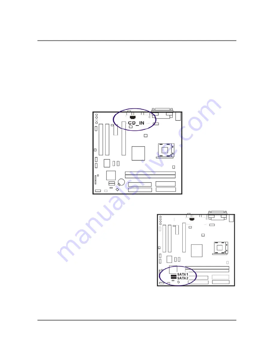
CD _In Connectors
The CD_IN connector is for CD-ROM drive audio analog input use. The pin
assignment are: Pin 1 is Left, Pin2 and 3 are GND, Pin 4 is Right.
Serial ATA Connectors
The 2 SATA connectors provide you with the
connections to serial ATA devices that confirm
to the Serial ATA specification. Serial ATA
supports all ATA and ATAPI devices. The
figures below left are two SATA cables (the top
one is for power; the next one is for data). The
data cable pin assignments of SATA connector.
Содержание PTM900
Страница 1: ...PTM900 MAINBOARD MANUAL DOC No M0590040 Rev A0 Date 12 2006 Part No 25 13031 00 ...
Страница 2: ...PTM900 Mainboard Manual 1 2 This page is intended to be blank ...
Страница 5: ...PTM900 Mainboard Manual 1 3 Chapter 1 Overview The PTM900 Mainboard ...
Страница 8: ...PTM900 Mainboard Manual 1 6 This page is intended to be blank ...
Страница 25: ...PTM900 Mainboard Manual 2 17 This page is intended to be blank ...
Страница 26: ......
Страница 32: ...PTM900 Mainboard Manual 3 6 Integrated Peripherals VIA OnChip IDE Device ...
Страница 40: ...PTM900 Mainboard Manual 3 14 This page is intended to be blank ...


