PTM900 Mainboard Manual
2- 5
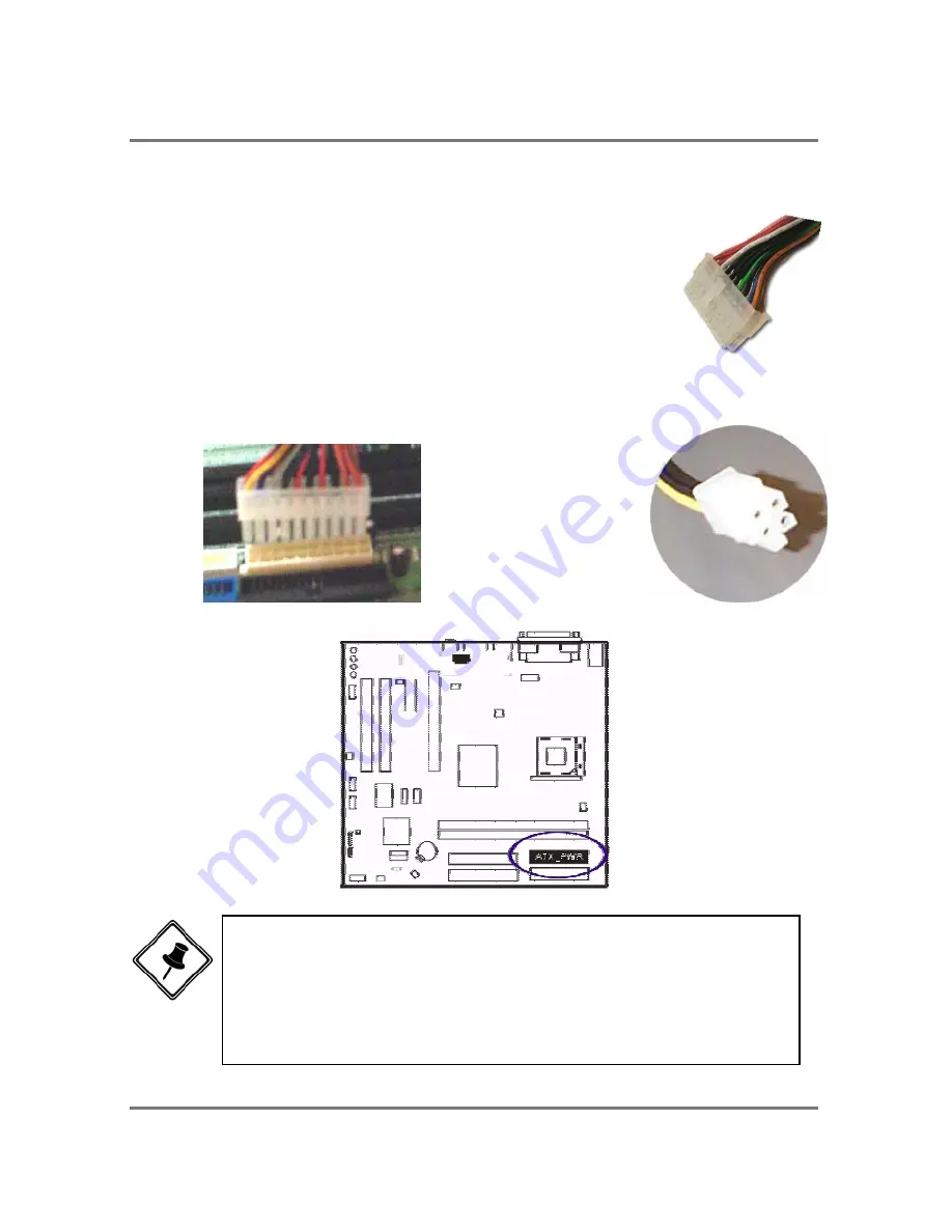
Connect ATX Power
The 24-hole power plug (top right) is connected to the ATX
power 24-pin pinheaders. The 4-hole 12V power plug (bottom
right) is inserted in the ATX_12V power connector.
The plug from the power supply will only insert in one
orientation because of the different hole sizes. Find the proper
orientation and push down firmly making sure that the pins are
aligned.
NOTE:
1. Insert the CPU (with fansink and retention module) on |socket.
2. Connect the 4-pin plug of the power supply
3. Connect the 24-pin plug of the power supply.
To remove the processor, please do it in reverse order.
Содержание PTM900
Страница 1: ...PTM900 MAINBOARD MANUAL DOC No M0590040 Rev A0 Date 12 2006 Part No 25 13031 00 ...
Страница 2: ...PTM900 Mainboard Manual 1 2 This page is intended to be blank ...
Страница 5: ...PTM900 Mainboard Manual 1 3 Chapter 1 Overview The PTM900 Mainboard ...
Страница 8: ...PTM900 Mainboard Manual 1 6 This page is intended to be blank ...
Страница 25: ...PTM900 Mainboard Manual 2 17 This page is intended to be blank ...
Страница 26: ......
Страница 32: ...PTM900 Mainboard Manual 3 6 Integrated Peripherals VIA OnChip IDE Device ...
Страница 40: ...PTM900 Mainboard Manual 3 14 This page is intended to be blank ...


