


TX150 S5
Service Supplement
39
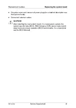
Replacement routines
Replacing the system board
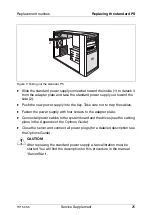
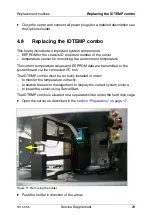
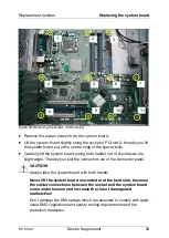
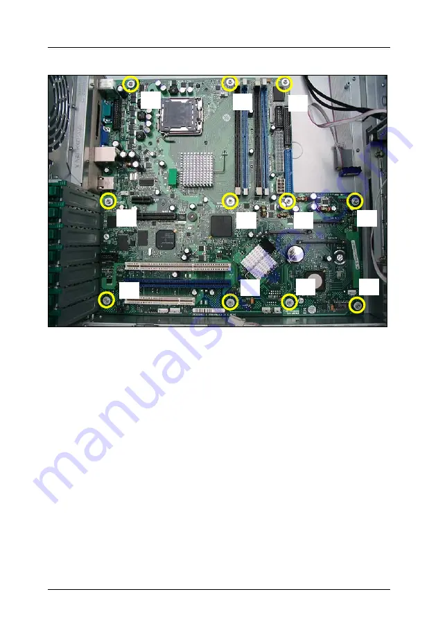
Figure 20: Removing the screws (SAS version)
Ê
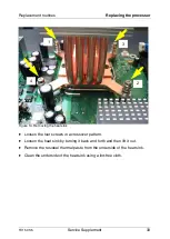
Remove the eleven screws from the system board.
Ê
Lift the system board slightly using the socket of PCI slot 5, thereby you lift
the system board out of the centre rings of the spacer bolts.
Ê
Carefully lift the system board (using both hands) out of the chassis in a
slight angle. Thereby you pull the connectors out of the connector panel.
V
CAUTION!
Always take the system board with both hands!
Never lift the system board one-sided or at the heat sink, because
the solder connections between the socket and the system board
come under tension and increase the risk of damage and
malfunction!
Don’t damage the EMI springs which are essential to comply with appli-
cable EMC regulations and satisfy cooling requirements and fire
protection measures.
1
2
3
4
5
7
8
9
6
11
10


