background image

28

Options Guide

 RX100 

S6

Population rules

5.1

Population rules

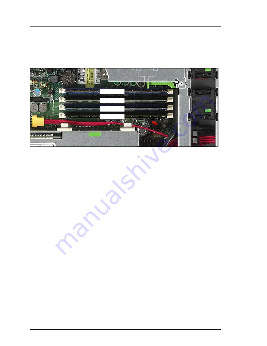
There are four slots for main memory. 

Figure 5: Slots of the main memory

Memory slot 1 / channel A (DIMM 1A) needs to be populated first.

Quad rank (QR) memory modules must be populated first in DIMM 1A, in 
case of usage memory modules with different ranks (SR/DR + QR). 

Within all channels memory slot 1 must be populated prior to slot 2.

Install memory modules within a channel in descending order of capacity: 
higher capacity in slot 1, lower capacity in slot 2.

Mixing of RDIMM and UDIMM is not allowed.

DIMM 2A
DIMM 1A
DIMM 2B
DIMM 1B

Содержание PRIMERGY RX100 S6

Страница 1: ...Options Guide English PRIMERGY RX100 S6 Server Options Guide Edition February 2011 ...

Страница 2: ... Copyright and Trademarks Copyright 2011 Fujitsu Technology Solutions GmbH All rights reserved Delivery subject to availability right of technical modifications reserved All hardware and software names used are trademarks of their respective manufacturers The contents of this manual may be revised without prior notice Fujitsu assumes no liability for damages to third party copyrights or other righ...

Страница 3: ...the mouse and keyboard are limited life components Use of these components beyond their operating life may result in electrolyte leakage or depletion potentially causing emission of foul odor or smoke As a guideline in a normal office environment 25 C operating life is not expected to be reached within the maintenance support period 5 years However operating life may be reached more quickly if for...

Страница 4: ...uter issued by JEITA the Japan Electronics and Information Technology Industries Association Technology controlled by the Foreign Exchange and Foreign Trade Control Law of Japan Documents produced by Fujitsu may contain technology controlled by the Foreign Exchange and Foreign Trade Control Law of Japan Documents which contain such technology should not be exported from Japan or transferred to non...

Страница 5: ...Options Guide Only for the Japanese market I Although described in this manual some sections do not apply to the Japanese market These options and routines include USB Flash Module UFM CSS Customer Self Service ...

Страница 6: ...OptionsGuide RX100 S6 ...

Страница 7: ...tions 12 2 Procedure 13 3 Safety instructions 15 4 Preparation 23 4 1 Opening the server 23 5 Main memory 27 5 1 Population rules 28 5 2 Expanding the main memory 30 6 Accessible drives and LSP 31 6 1 Installing an accessible 5 25 inch slimline drive 32 6 2 Installing a LSP 35 7 Expansion cards and BBU 39 7 1 Installing an expansion card 40 7 2 Installing a BBU 51 ...

Страница 8: ...OptionsGuide RX100 S6 Contents 8 Further options 55 8 1 Front VGA module 55 8 2 TPM 57 8 3 USB Flash Module UFM 59 9 Completion 63 9 1 Closing the server 63 10 Appendix 67 10 1 Cabling 67 Index 75 ...

Страница 9: ...end and upgrade your server V CAUTION The activities described in this manual may only be performed by technical specialists I The installation and removal of the hot plug components is described in the Operating Manual supplied with the server 1 2 Documentation overview More information on your PRIMERGY RX100 S6 can be found in the following documents Quick Start Hardware PRIMERGY RX100 S6 leafle...

Страница 10: ...he order number U15000 C289 the order number for the Japanese market please refer to the configurator of the server http primeserver fujitsu com primergy system html The PDF files of the manuals can also be downloaded free of charge from the Internet The overview page showing the online documentation available on the Internet can be found using the URL for EMEA market http manuals ts fujitsu com T...

Страница 11: ... Panel LSP for an easier identification of the defective components I There is only one 3 5 inch bay You can install either a LSP or a Front VGA module Additional expansion cards in the PCI slots With two riser cards the system board offers 2 x PCI Express x8 slots and 1x PCI Express x4 slot BBU You can install one Battery Backup Unit BBU Front VGA module The server can be equipped with a Front VG...

Страница 12: ...otational conventions are used in this manual Text in italics indicates commands or menu items Quotation marks indicate names of chapters and terms that are being emphasized Ê describes activities that must be performed in the order shown V CAUTION pay particular attention to texts marked with this symbol Failure to observe this warning may endanger your life destroy the system or lead to the loss...

Страница 13: ... that all necessary manuals see the section Documentation overview on page 9 are available print the PDF files if required Most importantly you will need the Operating Manual for the server and the Technical Manual for the system board Ê Shut the server down correctly switch it off disconnect the power cords and open the server as described in the chapter Preparation on page 23 Ê Carry out the exp...

Страница 14: ...14 OptionsGuide RX100 S6 Procedure ...

Страница 15: ...o is trained to install the server including hardware and software Repairs to the device that do not relate to CSS failures shall be performed by service personnel Please note that unauthorized interference with the system will void the warranty and exempt the manufacturer from all liability Any failure to observe the guidelines in this manual and any improper repairs could expose the user to risk...

Страница 16: ...ks and jolts Installation and operation V CAUTION This unit should not be operated in ambient temperatures above 35 C If the unit is integrated into an installation that draws power from an industrial power supply network with an IEC309 connector the power supply s fuse protection must comply with the requirements for non industrial power supply networks for type A connectors The unit automaticall...

Страница 17: ...ded Ethernet cabling has to comply with EN 50173 and EN 50174 1 2 standards or ISO IEC 11801 standard respectively The minimum requirement is a Category 5 shielded cable for 10 100 Ethernet or a Category 5e cable for Gigabit Ethernet Route the cables in such a way that they do not create a potential hazard make sure no one can trip over them and that they cannot be damaged When connecting the serv...

Страница 18: ...ranty is void if the server is damaged during installation or replacement of system expansions Only set screen resolutions and refresh rates that are specified in the operating manual for the monitor Otherwise you may damage your monitor If you are in any doubt contact your sales outlet or customer service center Before installing removing internal options to from the server turn off the server al...

Страница 19: ... on this note is sometimes changed to the kind of possible options without notice Batteries V CAUTION Incorrect replacement of batteries may result in a risk of explosion The batteries may only be replaced with identical batteries or with a type recommended by the manufacturer see the Technical Manual for the system board Replace the lithium battery on the system board in accordance with the instr...

Страница 20: ...ment damage and can fly out of the device danger of injury particularly to uncovered body parts such as the face or neck High humidity and airborne dust levels are to be avoided Electric shocks and or server failures may be caused by liquids such as water or metallic items such as paper clips entering a drive Shocks and vibrations are also to be avoided Do not insert any objects other than the spe...

Страница 21: ...the CD DVD BD with a soft dry cloth then let it air dry Do not dry the CD DVD BD using devices such as a hair dryer To avoid dust damage and deformation keep the CD DVD BD in its case whenever it is not in use Do not store CDs DVDs BDs at high temperatures Areas exposed to prolonged direct sunlight or near heating appliances are to be avoided I You can prevent damage from the optical drive and the...

Страница 22: ... discharge static build up e g by touching a grounded object before working with such components Any devices or tools that are used must be free of electrostatic charge Wear a suitable grounding cable that connects you to the external chassis of the system unit Always hold components with ESDs at the edges or at the points marked green touch points Do not touch any connectors or conduction paths o...

Страница 23: ...ip over Only for rack model Be careful not to pinch fingers or clothes when sliding out the server or pushing it back Failure to do so may cause injury Before attaching the cover make sure no unnecessary parts or tools are left inside the server Before turning on the server make sure the cover is closed Follow the safety instructions in the chapter Safety instructions on page 15 4 1 Opening the se...

Страница 24: ... 1 Ê Pull the server as far as it will go out of the rack 2 Ê Release the locking mechanism a or b of both rails 3 Ê Pull the server carefully out of the rails and place it on a flat support Figure 3 Loosening the two knurled screws Ê Unlock the top cover by removing the two knurled screws at the rear side 1 0 1 B C 0 0 ...

Страница 25: ...RX100 S6 Options Guide 25 Opening the server Figure 4 Removing the top cover Ê Push the top cover as far as it will go in the direction of the arrow 1 Ê Lift off the top cover upward 2 0 1 ...

Страница 26: ...26 OptionsGuide RX100 S6 Opening the server ...

Страница 27: ...g so may cause electric shock a fire or failures Wait for a sufficient period of time after server shutdown before installing or removing memory modules Failure to do so may cause burns When installing or removing memory modules make sure to remove the screws at the specified points only Failure to do so may cause injury It may also cause failures Touch only the specified part of the printed circu...

Страница 28: ...rst Quad rank QR memory modules must be populated first in DIMM 1A in case of usage memory modules with different ranks SR DR QR Within all channels memory slot 1 must be populated prior to slot 2 Install memory modules within a channel in descending order of capacity higher capacity in slot 1 lower capacity in slot 2 Mixing of RDIMM and UDIMM is not allowed DIMM 2A DIMM 1A DIMM 2B DIMM 1B ...

Страница 29: ...nfiguration per channel Max speed DIMM 2 DIMM 1 1 DDR3 1333 empty SR DR 2 DDR3 1066 empty QR 3 DDR3 1333 SR DR SR DR 4 DDR3 800 QR QR Technology DDR3 1333 unbuffered single rank SR or dual rank DR UDIMM memory modules with ECC Support for up to 4 UDIMM memory modules UDIMM memory modules are supported by Intel Dual Core processors e g Core i3 540 Pentium G6950 Celeron G1101 and by Intel Quad Core ...

Страница 30: ... the securing clips Ê Press the securing clips on both sides of the memory slot concerned outward 1 Figure 7 Installing a memory module Ê Carefully press the memory module into the slot 1 until the securing clips on both sides of it engage 2 Ê Close the server connect it to the power outlet and switch it on as described in the chapter Completion on page 63 0 0 0 1 1 ...

Страница 31: ... the circuitry on boards and soldered parts Hold the metallic areas or the edge of the circuit boards The circuit boards and soldered parts of internal options are exposed and can be damaged by static electricity Before handling them first touch a metal part on the server to discharge static electricity from your body Before installing an internal accessible drive see the manual for the accessible...

Страница 32: ...e Ê Pull the dummy cover out of the bay 1 V CAUTION Keep the dummy cover for future use If you remove the accessible drive again and do not replace it with a new one the dummy cover must be reinstalled to comply with EMC regulations and to satisfy cooling requirements and fire protection measures Figure 9 Removing the retaining spring from the dummy cover Ê Remove the two screws 1 Ê Pull the retai...

Страница 33: ...ng the retaining spring Ê Fasten the retaining spring with two screws to the rear side of the accessible drive Figure 11 Installing the accessible drive Ê Push the accessible drive into the bay 1 simultanously pressing the front of the drive slightly down until the retaining spring engages 2 0 1 ...

Страница 34: ...e data cable 2 to the SATA connector on the accessible drive see the cabling plans in the Appendix Figure 13 Connecting the SATA cable to the system board Ê Thread the SATA cable through the openings 1 Ê Connect the SATA cable 2 to the system board see the cabling plans in the Appendix Ê Close the server connect it to the power outlet and switch it on as described in the chapter Completion on page...

Страница 35: ... 2 Installing a LSP I There is only one 3 5 inch bay You can install either a LSP or a Front VGA module Ê Open the server as described in the chapter Preparation on page 23 Figure 14 Disengaging the dummy module Ê Press the locking mechanism down ...

Страница 36: ... module frontward and out of the bay V CAUTION Keep the dummy module for future use If the LSP is removed again and not replaced with a new one then the dummy module must be reinstalled due to cooling the applicable EMC regulations regulations on electromagnetic compatibility and fire protection ...

Страница 37: ...RX100 S6 Options Guide 37 Installing a LSP Figure 16 LSP Figure 17 Installing the LSP Ê Push the LSP into the bay from the front until the locking mechanism engages ...

Страница 38: ...he LSP cable 2 to the LSP see the cabling plans in the Appendix Figure 19 Connecting the LSP cable to the system board Ê Plug the LSP cable into the SMBus LSP connector on the system board see the cabling plans in the Appendix Ê Close the server connect it to the power outlet and switch it on as described in the chapter Completion on page 63 1 0 ...

Страница 39: ...ilure to do so can cause electric shock The circuit boards and soldered parts of internal options are exposed and can be damaged by static electricity Before handling them first touch a metal part on the server to discharge static electricity from your body Do not touch the circuitry on boards and soldered parts Hold the metallic areas or the edge of the circuit boards Follow the safety instructio...

Страница 40: ...tandard or low profile PCIe x8 slot maximum length 175 mm S26361 E403 A10 PCIe x8 1 slot 2 low profile PCIe x8 slot maximum length 170 mm PCIe x4 mech x8 1 slot 3 PCIe x4 slot mech x8 only for modular RAID 1 Controller for special slots PCI bus type Max pcs per system Slot no Forbidden slot 1 2 Nvidia NVS290 S26361 F2748 E63 only when slot 3 is empty 1 2 1 3 Intel 10 Gigabit XF SR Dual Port S26361...

Страница 41: ...2 1 2 3 Intel Pro 1000PT dual Server Adapter S26361 F3228 E201 Redwater 2 1 2 3 Intel PRO 1000 PF Server Adapter S26361 F3242 E201 Sheepshead Bay 4 GB s 2 1 2 3 3 PCI Express x1 controller PCI bus type Max pcs per system Slot no Forbidden slot 1 2 Adaptec SCSI Card ASC 29320LPE S26361 F3270 E201 4 GB s 1 1 2 3 Intel Gigabit CT Desktop Adapter S26361 F3516 E201 Shelter Island 2 1 2 3 Intel PRO 1000...

Страница 42: ...Open the server as described in the chapter Preparation on page 23 Figure 20 Removing the riser module 1 Ê Push the green lock bars of the riser module 1 in direction of the arrows 1 Ê Carefully pull out the riser module 1 upward 2 Ê Please read the documentation supplied with the expansion card 0 1 0 ...

Страница 43: ...ON Keep the slot cover for future use If the expansion card is removed and not replaced with a new card the slot cover must be reinstalled due to cooling to comply with applicable EMC regulations regulations on electromagnetic compatibility and to protect against fire Figure 22 Removing the slot cover extension Ê Loosen the screw 1 and remove the slot cover extension 2 1 0 1 0 ...

Страница 44: ...r extension to the slot cover of the expansion card 1 Ê Fasten the slot cover extension with one screw 2 Figure 24 Installing an expansion card slot 1 Ê Carefully press the expansion card into the riser card slot A until it clicks into place 1 Make sure that the lug on the slot cover B clicks into place in the corresponding hole 2 1 0 1 0 A B ...

Страница 45: ... the two guiding bolts A at the right side of the riser holder engage correctly Ê Push the green lock bars of the riser module 1 in direction of the arrows 2 Ê If necessary connect the cables to the expansion card and the other components Ê Close the server connect it to the power outlet and switch it on as described in the chapter Completion on page 63 0 1 1 A ...

Страница 46: ... Open the server as described in the chapter Preparation on page 23 Figure 26 Removing the riser module 2 Ê If necessary remove the cables from the two cable clamps 1 Notice the cable routing Ê Carefully pull out the riser module 2 upward 2 Ê Please read the documentation supplied with the expansion card 1 0 0 ...

Страница 47: ... Pull out the slot cover 1 V CAUTION Keep the slot cover for future use If the expansion card is removed and not replaced with a new card the slot cover must be reinstalled due to cooling to comply with applicable EMC regulations regulations on electromagnetic compatibility and to protect against fire ...

Страница 48: ...sion card Figure 28 Installing an expansion card slot 2 Ê Carefully press the expansion card into the riser card slot A until it clicks into place 1 Make sure that the lug on the slot cover B clicks into place in the corresponding hole 2 1 0 A B ...

Страница 49: ...ounting bracket to the expansion card 1 Ê Fasten the mounting bracket with two screws 2 Figure 30 Installing an expansion card slot 3 Ê Fit the hook on the riser card holder B into the retaining slot in the mounting bracket 1 Ê Carefully press the expansion card into the riser card slot A until it clicks into place 2 1 0 1 1 0 A B ...

Страница 50: ...Make sure that the two guiding bolts A of the riser holder engage correctly Ê If necessary route the cables in the two cable clamps as before 2 Ê If necessary connect the cables to the expansion card and the other components Ê Close the server connect it to the power outlet and switch it on as described in the chapter Completion on page 63 1 0 1 A ...

Страница 51: ...bed in the chapter Preparation on page 23 Figure 32 Removing two bolts from the BBU Ê Loosen the two screws and remove the two bolts from the BBU Figure 33 Connecting the cable to the BBU Ê Connect the BBU cable to the BBU V CAUTION Make sure that the connector side with two pin rows A is on the top Otherwise you risk short circuits A ...

Страница 52: ...gure 34 Position of the bolts and the foil Figure 35 Fastening the BBU to the housing Ê Position the BBU on the two bolts in the housing 1 with aligning the edges of the foil A and the BBU Ê Fasten the BBU to the bolts using two screws 2 1 0 A 1 ...

Страница 53: ...ion card on page 40 Ê Connect the BBU cable to the controller V CAUTION Make sure that the connector side with two pin rows is on the top Otherwise you risk short circuits Figure 37 Routing BBU cable Ê Route the BBU cable as shown in the figure Ê Close the server connect it to the power outlet and switch it on as described in the chapter Completion on page 63 ...

Страница 54: ...54 OptionsGuide RX100 S6 Installing a BBU ...

Страница 55: ...ither a LSP or a Front VGA module Ê Open the server as described in the chapter Preparation on page 23 Ê Remove the dummy module as described on page 35 Figure 38 Connecting cables to the Front VGA module Ê Thread the two ends of the Front VGA cable through the top bay for accessible drives 1 Ê Connect the USB connector 2 and the VGA connector 3 to the connectors of the Front VGA module 1 2 0 1 2 ...

Страница 56: ...ead the cable through the openings 2 Figure 40 Connecting the Front VGA cable to the system board Ê Connect the Front VGA cable to the system board see the cabling plans in the Appendix Ê Route the cable in the two cable clamps Ê Close the server connect it to the power outlet and switch it on as described in the chapter Completion on page 63 0 1 ...

Страница 57: ...igure 41 TPM installation kit Ê Open the server as described in the chapter Preparation on page 23 Figure 42 Inserting the TPM spacer on the system board Ê Insert the TPM spacer into the hole on the system board 1 TPM Trusted Platform Module 3 Special screw for TPM 2 TPM spacer I The black TPM spacer is not used in this server 4 TPM screwdriver insert bit for TPM special screw 햲 햳 햴 햵 ...

Страница 58: ...sten the TPM with the special screw for the TPM 2 Please use the TPM screwdriver insert bit to tighten the special screw I Do not fasten the screw too tightly torque value of 0 6 Nm Ê Close the server connect it to the power outlet and switch it on as described in the chapter Completion on page 63 0 1 ...

Страница 59: ... USB Flash Module UFM 8 3 USB Flash Module UFM The server can be equipped with a USB Flash Module UFM Figure 44 UFM installation kit Figure 45 UFM cable 1 USB Flash Module UFM 3 UFM spacer 2 UFM nylon screw 4 UFM cable 0 1 2 3 ...

Страница 60: ...USB Flash Module UFM Ê Open the server as described in the chapter Preparation on page 23 Figure 46 Preparing the UFM Ê Remove the nylon screw from the UFM 1 Ê Remove the UFM spacer 2 I The UFM spacer is no longer required 햳 햲 ...

Страница 61: ...Options Guide 61 USB Flash Module UFM Figure 47 Position of the bolts in the chassis Figure 48 Positioning the UFM Ê Push the UFM between the two bolts 1 until the threaded bolt 2 engages in the screw hole 1 0 0 ...

Страница 62: ...Fasten the UFM with the nylon screw Figure 50 Connecting the UFM cable Ê Connect the UFM cable to the UFM connector J2 and to the system board connector J26 Ê Close the server connect it to the power outlet and switch it on as described in the chapter Completion on page 63 1 0 ...

Страница 63: ...s in chapter Safety instructions on page 15 9 1 Closing the server Figure 51 Mounting the top cover Ê Place the top cover on the server 1 Make sure that each bolt is positioned in the corresponding nut Ê Push the top cover as far as it will go in the direction of the arrow 2 0 1 ...

Страница 64: ...he two knurled screws at the rear side 1 If you have not removed the server from the rack skip the instructions for mounting in the rack Figure 53 Inserting the server Ê Extend the interior telescopic rails completely to the front 1 I They must click into place so that they can no longer be moved 0 0 3 1 3 3 1 0 B C ...

Страница 65: ...ase the locking mechanism a or b of both rails 3 Ê Push the server as far as it will go into the rack 4 Ê Fasten the server to the rack 5 using the two knurled screws front panel Ê Reconnect all the cables you disconnected beforehand on the rear of the server Ê Connect all power plugs to the power outlets Ê Press the on off key to start up the server ...

Страница 66: ...66 OptionsGuide RX100 S6 Closing the server ...

Страница 67: ...e 4 SNP A3C40108860 System board to ODD data 5 SNP A3C40102759 System board to backplane SATA only 6 SNP A3C40102800 System board to LSP 7 SNP A3C40102801 System board to front VGA module 8 SNP A3C40102755 System board to backplane SATA only 9 SNP A3C40102760 System board to backplane SATA only 10 SNP A3C40102805 RAID card to backplane 11 SNP A3C40114082 RAID card to backplane 12 T26361 Y3987 V2 i...

Страница 68: ...68 OptionsGuide RX100 S6 Cabling Figure 54 Basic cabling HDD bay HDD bay 350W PSU Slim ODD System fans 2 1 4 CPU Front panel 1 2 4 SNP A3C40102754 SNP A3C40102753 SNP A3C40108860 ...

Страница 69: ...ling of the 2 5 inch SATA HDD variant HDD bay HDD bay 350W PSU Slim ODD System fans 2 1 4 CPU Front panel 1 SNP A3C40102754 2 SNP A3C40102753 4 SNP A3C40108860 9 8 Backplane 5 3 3 SNP A3C40102758 5 SNP A3C40102759 8 SNP A3C40102755 9 SNP A3C40102760 ...

Страница 70: ...f the 2 5 inch SAS HDD variant with iBBU HDD bay HDD bay 350W PSU Slim ODD System fans 2 1 4 CPU Front panel 1 SNP A3C40102754 2 SNP A3C40102753 4 SNP A3C40108860 Backplane 3 3 SNP A3C40102758 SNP A3C40102805 12 T26361 Y3987 V2 RAID card 10 10 iBBU 10 12 ...

Страница 71: ...ure 57 Cabling of the 3 5 inch SATA HDD variant HDD bay HDD bay 350W PSU Slim ODD System fans 2 1 4 CPU Front panel 1 SNP A3C40102754 2 SNP A3C40102753 4 SNP A3C40108860 Backplane 5 3 3 SNP A3C40102758 5 SNP A3C40102759 8 SNP A3C40102755 8 ...

Страница 72: ...f the 3 5 inch SAS HDD variant with iBBU HDD bay HDD bay 350W PSU Slim ODD System fans 2 1 4 CPU Front panel 1 SNP A3C40102754 2 SNP A3C40102753 4 SNP A3C40108860 Backplane 3 SNP A3C40102758 SNP A3C40114082 12 T26361 Y3987 V2 RAID card 11 iBBU 11 12 3 11 ...

Страница 73: ...inch SATA HDD variant with Front VGA module HDD bay HDD bay 350W PSU System fans 2 1 4 CPU Front panel 1 SNP A3C40102754 2 SNP A3C40102753 4 SNP A3C40108860 Backplane 5 3 3 SNP A3C40102758 5 SNP A3C40102759 7 SNP A3C40102801 Front VGA module 8 8 SNP A3C40102755 7 7 ...

Страница 74: ...g of the 3 5 inch SATA HDD variant with LSP HDD bay HDD bay 350W PSU System fans 2 1 4 CPU Front panel 1 SNP A3C40102754 2 SNP A3C40102753 4 SNP A3C40108860 Backplane 5 3 3 SNP A3C40102758 5 SNP A3C40102759 6 SNP A3C40102800 LSP 8 8 SNP A3C40102755 6 ...

Страница 75: ...40 F Front VGA module 11 55 I information additional 10 L laser information 21 light emitting diode LED 21 lithium battery 19 M main memory 11 meaning of the symbols 12 N notational conventions 12 R riser card 40 S security function 9 ServerView Local Service Panel 11 35 T target group 9 top cover 24 63 64 TPM 11 57 U UFM 12 59 USB Flash Module 12 59 ...

Страница 76: ...76 OptionsGuide RX100 S6 Index ...

Отзывы: