


86
Operating Manual
BX900S2
Starting up and operation
©
c
og
ni
ta
s.
Ges
el
ls
ch
ft f
ü
r T
e
ch
ni
k-
D
ok
um
e
nt
a
tio
n m
bH
201
2
P
fad
: C
:\P
ro
gr
am
m
e\
F
C
T
\ti
m
_
app
\ti
m
_
loc
al
\w
o
rk
\WA
LT
E
R
\O
B
J_D
OK
U
-13
57
0-
00
1.
fm
6.1.3.6
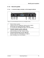
Connection Blade 8Gb FC Switch 18/8
Figure 27: 8-Gb FC Switch Connection Blade 18/8
1
ID
ID indicator (blue)
Lit:
ID indicator was activated via the management blade
2
Health indicator (green/orange)
Controlled by the management blade
3
Reset button
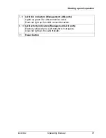
4
Status indicator (green/orange)
Dark:
Connection blade is not running or is defective
Lights up green:
Connection blade is running
Lights up orange:
Boot phase; one or more ports are offline; restarting connection
Flashes
orange/green:
Warning: An error has occurred.
The LED can also flash during a test.
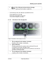
A
External FC ports
(8x)
Ports for FC SFP Multi-Mode (MMF) or FC SFP+ Multi-Mode (MMF) SFP modules
B
Status indicators for external FC ports (green/orange)
Dark:
No signal reception
Flickers green:
FC port online, data transport
Flashes green:
–
Slow: FC port online, but segmented
–
Fast: Internal loop
Lights up orange:
Signal reception, but not online
Flashes orange:
Slow (~ 2 sec. interval): FC port deactivated.
Fast (~ 0.5 sec. interval): FC port defective
C
Management LAN port
1 2 3
C
A
B
4