


C141-E110-02EN
4 - 14
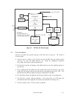
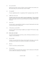
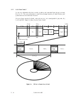
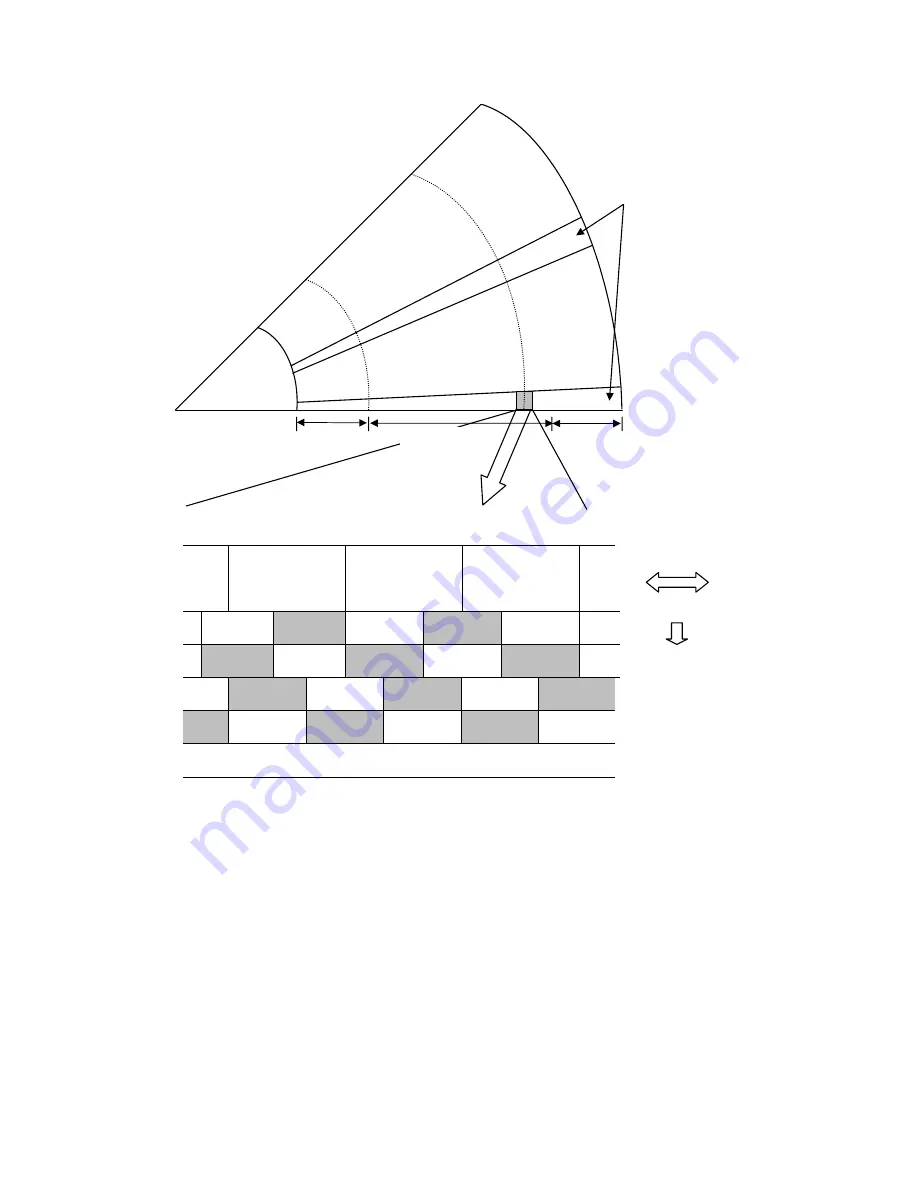
Figure 4.5
Physical sector servo configuration on disk surface
(2)
Servo burst capture circuit
The four servo signals can be synchronously detected by the STROB signal, full-wave rectified
integrated.
(3)
A/D converter (ADC)
The A/D converter (ADC) receives the servo signals are integrated, converts them to digital, and
transfers the digital signal to the DSP unit.
OGB
Data area
IGB
expand
Servo frame
(126 servo frames per revolution)
CY1 n + 1
CY1 n
CY1 n – 1 (n: odd number)
Diameter direction
Circumference d
irection
Erase: DC erase area
W/R Recovery
Servo Mark
Gray Code
W/R Recovery
Servo Mark
Gray Code
W/R Recovery
Servo Mark
Gray Code
Erase
Servo A
Erase
Servo A
Erase
Servo B
Erase
Servo B
Erase
Servo B
Servo C
Erase
Servo C
Erase
Erase
Servo D
Erase
Servo D
PAD
Содержание MPG3xxxAT
Страница 1: ...C141 E110 02EN MPG3xxxAT DISK DRIVES PRODUCT MANUAL ...
Страница 3: ...This page is intentionally left blank ...
Страница 15: ...This page is intentionally left blank ...
Страница 31: ...C141 E110 02EN 3 2 Figure 3 1 Dimensions ...
Страница 47: ...This page is intentionally left blank ...
Страница 67: ...This page is intentionally left blank ...
Страница 177: ...This page is intentionally left blank ...
Страница 201: ......