C141-E110-02EN
3 - 11
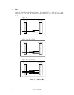
open
Connector 2
Connector 1
System Board
Connector
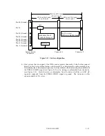
Pin 2 (Ground)
Pin 19 (Ground)
Pin 22 (Ground)
Pin 24 (Ground)
Pin 26 (Ground)
Position 1
Pin 34 contact
(PDIAG-:CBLID- signal)
254.0 to 457.2 mm
(10 to 18 inch)
101.6 to 152.4 mm
(4 to 6 inch)
127.0 to 304.8 mm
(5 to 12 inch)
Symbolizes Pin 34
Conductor being cut
Pin 30 (Ground)
Pin 34
Pin 40 (Ground)
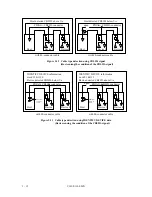
Figure 3.11 Cable configuration
b) Host system that do support Ultra DMA modes greater than mode 2 shall either connect
directly to the device without using a cable assembly, or determine the cable assembly type.
Determining the cable assembly type may be done either by the host sensing the condition of
the PDIAG-:CBLID- signal (see Figure 3.12), or by relying on information from the device
(see Figure 3.13). Hosts that rely on information from the device shall have a 0.047
µ
F
capacitor connected from the PDIAG-:CBLID- signal to ground. The tolerance on this
capacitor shall be 20% or less.
Содержание MPG3xxxAT
Страница 1: ...C141 E110 02EN MPG3xxxAT DISK DRIVES PRODUCT MANUAL ...
Страница 3: ...This page is intentionally left blank ...
Страница 15: ...This page is intentionally left blank ...
Страница 31: ...C141 E110 02EN 3 2 Figure 3 1 Dimensions ...
Страница 47: ...This page is intentionally left blank ...
Страница 67: ...This page is intentionally left blank ...
Страница 177: ...This page is intentionally left blank ...
Страница 201: ......

