C141-E166
4-5
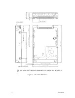
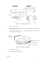
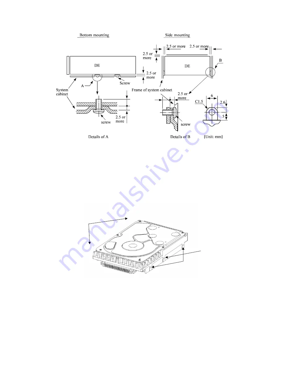
Figure 4.4
Mounting frame structure
(2)
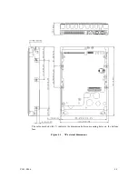
Limitation of side-mounting
Mount the IDD using the 4 screw holes at the both ends on the both sides as shown in Figure 4.5.
Do not use the center hole by itself.
In case of using the center hole, it must be used in combination with 2 holes on both ends.
(Total 6 screws for 6 holes enclosed)
Figure 4.5
Limitation of side-mounting
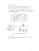
(3)
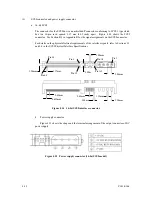
Limitation of bottom-mounting
Use all 4 mounting holes on the bottom face.
4
3
2
1
Use four holes (No.1-4) to mount.
Holes for
mounting screw.
Holes for mounting screw.
Do not use these holes
5.0 or less
5.0 or less
Содержание MAP3147NC - Enterprise - Hard Drive
Страница 1: ...C141 E166 01EN MAP3147NC NP MAP3735NC NP MAP3367NC NP DISK DRIVES PRODUCT MAINTENANCE MANUAL ...
Страница 10: ...This page is intentionally left blank ...
Страница 14: ...This page is intentionally left blank ...
Страница 18: ...This page is intentionally left blank ...
Страница 36: ...This page is intentionally left blank ...
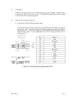
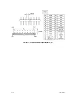
Страница 66: ...4 14 C141 E166 Figure 4 17 External operator panel connector CN2 ...
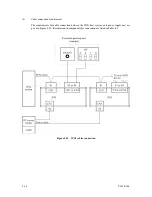
Страница 88: ...5 14 C141 E166 Motor starts when power is turned on Figure 5 4 Checking the SCSI connection A 60 ...
Страница 122: ...This page is intentionally left blank ...
Страница 126: ...This page is intentionally left blank ...
Страница 128: ...This page is intentionally left blank ...
Страница 130: ...This page is intentionally left blank ...
Страница 131: ......
Страница 132: ......

