Fujitsu F2MC-16LX FAMILY, Руководство по установке
Семейство микроконтроллеров Fujitsu F2MC-16LX представлено на нашем сайте для бесплатного скачивания инструкций по установке и пользованию. Этот мануал доступен для загрузки с manualshive.com. Получите всю необходимую информацию о продукте прямо сейчас!
Поделиться
Скачать


Отзывы:
Нет отзывов
Похожие инструкции для F2MC-16LX FAMILY

P2000
Бренд: Valex Страницы: 8

M2
Бренд: Kaller Страницы: 3

PDMH 4500 A1
Бренд: Parkside Страницы: 60

PA 5000
Бренд: UCAN Страницы: 22

ComfortCut 30
Бренд: Gardena Страницы: 14
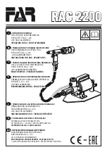
RAC 2200
Бренд: FAR Страницы: 56

KEN-503-1550K
Бренд: Kennedy Страницы: 2

DPU 4045H
Бренд: Wacker Neuson Страницы: 38

HM 200
Бренд: Uniflex Страницы: 44

RIGrunner
Бренд: West Mountain Radio Страницы: 7

EUSP175
Бренд: Astro Tool Страницы: 4

DC-D
Бренд: Hilti Страницы: 15

28D-1
Бренд: Secura Страницы: 8

UP711
Бренд: Urrea Страницы: 8

113395
Бренд: Far Tools Страницы: 23

XCS01
Бренд: Makita Страницы: 28

LXRH02
Бренд: Makita Страницы: 36

XWT01Z
Бренд: Makita Страницы: 28


