background image

25

Installing and removing an Expansion Card

 CAUTION

Please take note of the “Information about boards” chapter.

In the upper three slots you can install expansion cards with a length of up to 230 mm, and in the lower
slot expansion cards with a length of up to 315 mm.

The number, position and arrangement of the expansion card slots on the mainboard can be found in
the technical manual for the mainboard. Expansion cards may already be installed when the device
is shipped.

Installing an expansion card

1

Open the casing (see “Opening the casing”).

2

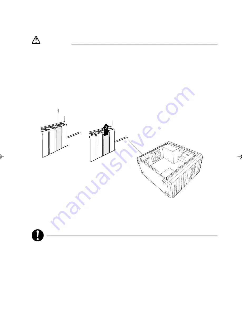
Remove the screw (1).

3

Remove the rear slot cover plate from the slot (2).

Do not dispose of the cover plate. For cooling, protection against fire and in order to comply
with EMC regulations, you must refit the cover plate if you remove the expansion card.
The top and the lowest slot are suitable for low-profile cards with an adapter.

4

Take the new expansion card out of its packaging.

P5100_4(20-28)

14/6/06, 2:29 pm

25

Содержание ESPRIMO P5100

Страница 1: ...tion in the U S Celeron is a registered trademark of Intel Corporation in the U S Other product names are trademarks or registered trademarks of respective companies Other products are copyrighted by individual companies All other trademarks referenced are trademarks or registered trademarks of their respective owners whose protected rights are acknowledged Copyright Fujitsu PC Asia Pacific All ri...

Страница 2: ...el If you are not sure of the type of power available consult your dealer or local power company 8 This product is equipped with a 3 wire grounding type plug a plug having a third grounding pin This will only plug into a grounding type power outlet This is a safety feature If you are unable to inserttheplugintotheoutlet contactyourelectriciantoreplaceyourobsoleteoutlet Donotdefeat the purpose of t...

Страница 3: ...takeextraprecautionModemcable whenconnectingtheLANanddonotconnectthecables to the peripheral device s connector that might have excessive voltage 16 CAUTION IftheCD DVDdriveisnotoperatedcorrectlyaccordingtotheinstructionsorprocedures specified in the operating manual it may emit a laser beam Disassembling the CD DVDdrivemaycauseyoutobeexposedtoaharmfullaserbeam Soneverdisassemble it The CD DVD dri...

Страница 4: ... disk and if they are used continuously for an extended period of time it may become necessary to replace them earlier than expected The components come with one year warranty warranty periods may vary depending on the type of contract Besides the useful life the brightness of the LCD monitor decreases with the time for which it is used Backing Up the Data Thecustomerisresponsibleformaintainingthe...

Страница 5: ...ftware 1 Use of and copyright on the Software You may use the Software solely on your computer You are granted a license to use the Software by purchasing the computer but the copyright on the Software remains the property of Fujitsu or its developer 2 Backup copy You may make one 1 copy of the Software solely for backup purposes 3 Incorporating the Software into other software If the Software is ...

Страница 6: ...l of safety which include but not limited to the following refers to systems that require an extremely high level of safety and may directly affect human lives and bodies if safety is not secured Nuclear energy control systems flight control systems air traffic control systems mass transportation operation and control systems life support systems and missile launchers in military facilities Keep t...

Страница 7: ...mber of security features to ensure that no unauthorised persons can access your data for example you can activate a screen saver with password protection The security functions in the BIOS Setup also allow you to protect your data by means of passwords Notational conventions The meanings of the symbols and fonts used in this manual are as follows Indicates information which is important for your ...

Страница 8: ...ounded mains outlet Caution components in the system can get very hot Manufacturer s notes Keep this operating manual together with your device If you pass on the device to third parties you should include this manual Energy saving When the PC is delivered some energy saving functions are already set If you are not using your PC switch it off In the BIOS Setup you may set further energy saving fun...

Страница 9: ...this equipment does cause harmful interference to radio or television reception which can be determined by turning the equipment off and on the user is encouraged to try to correct the interference by one or more of the following measures Reorient or relocate the receiving antenna Increase the separation between equipment and the receiver Connect the equipment into an outlet on a circuit different...

Страница 10: ...emove the power plug from the mains supply Do not clean any interior parts yourself leave this job to a service technician Do not use any cleaning agents that contain abrasives or may corrode plastic Ensure that no liquid enters the system Ensure that the ventilation areas of the system unit and the monitor are free Cleaning the system unit and the monitor Wipe the system unit and monitor casing w...

Страница 11: ...oser To individual customers LCD units should be disposed off as general waste Individual customers are advised to follow the disposal rules and regulations set forth by the local municipality Disposal of batteries The wireless keyboard and mouse use dry batteries These batteries may explode when inflamed Disposal of the batteries is controlled by the Waste Disposal and Public Cleaning Law To inst...

Страница 12: ...ric shock Unplug all power cords and LAN modem cables Warning and Caution Labels Your PC bears the warning and caution labels as shown below The warning and caution labels must not be removed or damaged Top of the PC main unit Inside the PC main unit Electric shock WARNING To prevent electric shock and or fire do not remove the cover of this unit which includes a high voltage section ...

Страница 13: ...ration Thissectiondescribesthelocationofinstallationandinstallationofthecomputer Chapter 3 Troubleshooting and Tips This chapter provides the basic information on the PC and operation Chapter 4 System Expansion Thischapterprovidesbasicinformationonhowtohandletheperipheralsinstalled or can be installed on the PC Organization of This Manual ...

Страница 14: ...tion Under Windows 15 BIOS Setup Security Functions 15 CHAPTER 3 Troubleshooting and Tips Troubleshooting and Tips 16 Installing New Software 16 Power on Indicator Remains Unlit after you have Switched on your Device 16 No Mouse Pointer Displayed on the Screen 18 The Floppy Disk Cannot be Read or Written 18 Time and or Date is not Correct 19 Error Messages on the Screen 19 Restoring the Hard Disk ...

Страница 15: ...irst time setup includes the connection of the monitor mouse and keyboard to the system unit and the setup of the supplied software External devices If you have received other devices in addition to your PC e g a printer or a modem do not connect these until after the initial installation Drives and boards If you have received drives or boards with your PC please do not install them until after fi...

Страница 16: ...lly We recommend that you place your equipment on a surface with good anti slip qualities In view of the multitude of different finishes and varnishes used on furniture it is possible that the rubber plastic feet of the devices will mark the surface they stand on Connect the Monitor Mouse and Keyboard The ports for monitor mouse and keyboard are on the rear and on the front of the system unit PS 2...

Страница 17: ...en you are requested to do so Otherwisetheinstallationwillbenotbeperformedcorrectly Ifafaultoccursduringtheinstallation the contents of the hard disk must be completely restored Switching on monitor and PC Switch the monitor on Switch the PC on To do this follow the instructions below Switching on PC with devices with main power switch 1 ON OFF switch Press the ON OFF switch on the front of the PC...

Страница 18: ...rounded mains outlets Connect all cables at the system unit and peripherals You must observe the information provided in the chapter Important notes Plug all data communication cables into the utility sockets Plug all power cables into the grounded mains outlets Disconnecting cables Turn off all power and equipment switches Pull all power plugs out of grounded mains outlets Unplug all data communi...

Страница 19: ...e marked with the symbols shown below or similar Keyboard port purple PS 2 mouse port green 1 Serial interface 1 turquoise Monitor port blue Parallel interface Printer burgundy Microphone jack mono pink Audio output Line out lime green Audio input Line in light blue USB Universal Serial Bus black LAN connector Some of the devices that you connect require special drivers see the operating system an...

Страница 20: ...ease install it from the data carrier supplied with the device or with the application programme Connecting external devices to the parallel port External devices can be connected to the parallel port e g a printer Connect the data cable to the external device Connect the data cable to the parallel port For an exact description of how to connect external devices to the parallel port please see the...

Страница 21: ...ows select Shut Down from the Start menu If the operating system does not automatically switch the PC off turn the PC to ready to operate when requested to do so by pressing the ON OFF switch If the PC is ready to operate the PC consumes very little power Switch off the PC at the power switch The PC no longer uses any power Themain powerswitchandthepowerbuttondonotdisconnectthePCfromthemainsvoltag...

Страница 22: ...used when the main unit of the personal computer is powered on Do not press this button when access indicator lights up 3 Headphone jack Connection jack for headphone While a headphone is being connected sound does not come out from the line out jack of the main unit of the personal computer or internal speakers 4 Microphone jack Connection jack for condenser microphone 5 USB ports Used to connect...

Страница 23: ...is button when the floppy disk access indicator lights up 10 Floppy disk drive optional Used to write data to a floppy disk or to read data from a floppy disk 11 Floppy disk access indicator Lights up when data is being written to a floppy disk or when data is read from a floppy disk 12 Built in 11 in 1 card reader writer The card reader writer allows users to copy data to and from the following m...

Страница 24: ...e main unit of the computer The side is On and the O side is Off If it is set to Off the main unit of the personal computer is not powered on even when pressing the power supply button However if you do not use the computer for a long time set it to Off 3 Mouse port Used to connect the mouse to the computer 4 Keyboard port Used to connect the keyboard to the computer ...

Страница 25: ... in it When the headphone is connected to the headphone jack sound does not come out from the line out jack of the main unit of the personal computer 10 Expansion card slot Insert the expansion card to expand the functions of the personal computer Expansion cards that support PCI can be used 11 Parallel port Used to connect to a printer or scanner 12 LAN port Used to connect the LAN cable 13 Line ...

Страница 26: ...de and overwrite mode 5 Print Screen key Pressing this button copies the screenshot to the clipboard 6 Home key Press the Home key to move the cursor all at once to the beginning of the current line or text 7 Indicators The indictor lights when you press Num Lock Shift Caps Lock or Scroll Lock indicating that it is enabled When the key is pressed again the indicator turns off and the key function ...

Страница 27: ... the Delete key to delete a character Press this key together with Ctrl and Alt to reset the computer 15 End key Press the End key to move the cursor all at once to the end of the current line or text 16 Cursor keys Press each of these keys to move the cursor in the desired direction 17 Page Down key Scrolls down the on screen page when pressed 18 Page Up key Scrolls up the on screen page when pre...

Страница 28: ...insert a floppy disk push it into the drive in the insertion direction until it engages The label should be facing upward To remove the floppy disk press the eject button 5 The write protect switch enables you to protect the data on the floppy disk from inadvertent overwriting or deletion To protect the data on the floppy disk from being overwritten push the write protect switch to position 6 The ...

Страница 29: ...orised opening of the casing Access Protection Under Windows Under MS Windows you can activate a screen saver and protect it with a password Only those userswhoknowthepasswordcandeactivatethescreensaverandaccessanyopenfiles Detailed information on screen savers is provided by the associated help function BIOS Setup Security Functions The Security menu in BIOS Setup offers you various options for p...

Страница 30: ...splayed Contact your sales outlet or our customer service centre Installing New Software When installing programs or drivers important files may be overwritten and modified To be able to access the original data in the event of any problems following installation you should backup your hard disk prior to installation Power on Indicator Remains Unlit after you have Switched on your Device This may ...

Страница 31: ...lease refer to the operating manual supplied with your monitor Power cable not connected Switch off the monitor and the PC Check that the monitor power cable of the monitor is properly connected to the monitor and depending on the connector to the PC or to the grounded mains outlet Check that the PC power cable is properly plugged into the PC and grounded mains outlet Switch on the monitor and the...

Страница 32: ...operating system properly Switch the PC off Check that the mouse cable is properly connected to the system unit If you use an adapter or extension lead with the mouse cable check the connections Make sure that only one mouse is connected Switch the PC on The mouse controller must be enabled if you use a PS 2 mouse Check in the BIOS Setup that the mouse controller is Enabled Check that the mouse dr...

Страница 33: ... are contained In the technical manual for the mainboard In the BIOS Setup manual In the documentation for the programmes used Restoring the Hard Disk Contents Should you need to restore your hard disk the instructions are provided with the Recovery CD delivered with your system Tips The PC cannot be switched off with the ON OFF switch Cause The PC was not switched on with the ON OFF switch Press ...

Страница 34: ...nboard Information about Boards Take care with the locking mechanisms catches and centring pins when you are replacing board or components on board To prevent damage to the board or the components and conductors on it please take care when you insert or remove boards Make sure expansion boards are inserted straightly Never use sharp objects screwdrivers for leverage Boards with electrostatic sensi...

Страница 35: ...er abnormal performance or failures of the computer caused by installing CD or DVD other than Fujitsu s products For devices that are not prepared by Fujitsu inquire the manufacture of peripheral devices you use about whether your computer supports these devices Your computer supports performances of Fujitsu s products only Install one peripheral device only at one time Installing two or more peri...

Страница 36: ...vices The power to peripheral devices is generally turned on before powering on the main unit of the personal computer however there are some peripheral devices that will be powered on after powering on the main unit of the personal computer Read the manual for peripheral devices Use ACPI support peripheral devices This personal computer supports ACPI one of the power control standards regarding e...

Страница 37: ...nnect them from the PC Place the system unit in a convenient working position Remove two screws 1 securing top cover Push the top cover in the direction of the arrow 2 Closing the casing Push the top cover down in the direction of the arrow 1 until it engages Install the two screws 2 to secure the top cover Return the PC to its original position If you have disconnected cables reconnect them to th...

Страница 38: ...ned When installing expansion cards use Fujitsu s products Otherwise it might cause an electronic shock fire or failure CAUTION Wheninstallingorremovingexpansioncards donotremovescrewsotherthan those specified Removingthescrewsotherthanspecifiedmightcauseinjuries Doingsomight also cause damage to your computer Do not touch the printed board other than areas specified Touching might cause injuries ...

Страница 39: ... in the technical manual for the mainboard Expansion cards may already be installed when the device is shipped Installing an expansion card 1 Open the casing see Opening the casing 2 Remove the screw 1 3 Remove the rear slot cover plate from the slot 2 Do not dispose of the cover plate For cooling protection against fire and in order to comply with EMC regulations you must refit the cover plate if...

Страница 40: ...sing 7 Press the expansion card into the slot so that it engages 8 Fasten the expansion card into place with the screw 2 9 If necessary connect the cables 10 Close the casing see Closing the casing If you have installed or removed a PCI card please check the relevant PCI slot settings in the BIOS Setup If necessary change the settings Further information is provided in the PCI card documentation 2...

Страница 41: ...d to the expansion card 3 Remove the screw 1 4 Remove the expansion card from the system unit 2 5 Place the expansion card into appropriate packaging CAUTION To ensure proper cooling fire protection and observation of the relevant EMC electromagnetic compatibility regulations you must mount a rear slot cover plate ...

Страница 42: ...over plate with the screw 2 8 Close the casing see Closing the casing CAUTION If you have installed or removed a PCI card please check the relevant PCI slot settings in the BIOS Setup If necessary change the settings Further information is provided in the PCI card documentation ...

Страница 43: ...w profile expansion cards in normal expansion card slots you must mount a corresponding slot adapter beforehand Mounting slot adapter Fit the slot adapter on the slot cover of the low profile expansion card 1 and screw it on 2 Now you can install the low profile board in a suitable slot like a normal expansion card see the chapter Installing expansion card Removing slot adapter Unscrew the screw 1...

Страница 44: ...e 1 Disconnect all cables connected to the drive data cable power supply cable 2 Unscrew the two screws holding the hard disk on bottom casing in the direction of arrow 1 and pull the hard disk out of the case in the direction of the arrow 2 It may be necessary to modify the entry for the drive in the BIOS Setup ...

Страница 45: ...guide provided with the hard disk 3 Slide the hard disk into the case in the direction of the arrow 2 4 Secure the hard disk to the casing by fastening two screws from the bottom of the case in the direction of the arrow 1 5 Connect the power and data cables to the hard disk drive 6 Close the casing see Closing the casing It may be necessary to modify the entry for the drive in the BIOS Setup ...

Страница 46: ...nment class 3K2 Environment class 2K2 Temperature Operating 3K2 Transport 2K2 Condensation in operating must be avoided Clearance required to ensure adequate ventilation left front rear ESPRIMO P5100 200 V 240 V 50 Hz 60 Hz 200 V 240 V 4 6A 180 mm 370 mm 365 mm 8 3kg in basic configuration DINIEC 721 part 3 3 DINIEC 721 part 3 2 10 C 35 C 10 C 60 C min 200 mm min 200 mm min 200 mm ...

Страница 47: ...withanyother USB support peripheral devices When USB 1 1 compliance peripheral devices are connected they can be used by specifications for USB 1 1 The max rating of USB devices is 500mA per port Please see the manual with the USB devices 4 To reduce energy consumption when powering off switch the main switch to the side or unplug the power plug from the AC cable 5 The power consumption is for sys...

Страница 48: ...34 ...

Отзывы: