


En-3
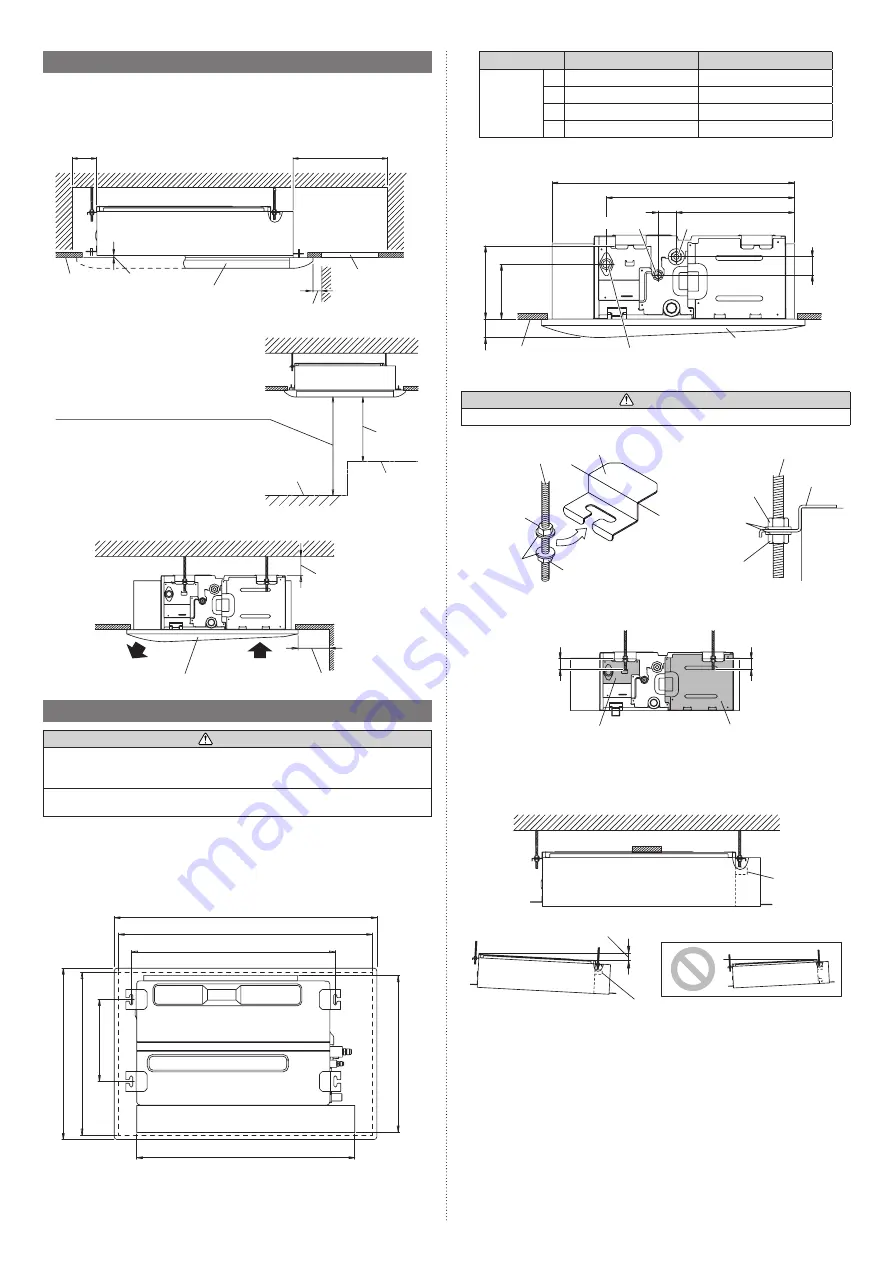
3.3. Installation dimensions
Provide a service access for inspection purposes.
Do not place any wiring or illumination in the service space, as they will impede service.
3.3.1. Installation dimensions
Front view
Service
space
Ceiling board
150 or more
Strong and durable ceiling
400 or more
5 to 10
20 or more
Cassette grille (optional parts)
Unit: mm
Service access
(recommend)
Floor
Maximum height from floor to ceiling
• Standard mode: 1800 to 2700
• High Ceiling mode: 1800 to 3200
*
Be sure to make the function settings with
the remote controller according to the
installed ceiling height.
1000 or
more
Obstruction
Unit: mm
Right side view
Air
Air
5 or more
Cassette grille (optional parts)
150 or more
Unit: mm
3.4. Installing the unit
WARNING
Install the air conditioner in a location which can withstand a load of at least 5 times the
weight of the main unit and which will not amplify sound or vibration. If the installation
location is not strong enough, the indoor unit may fall and cause injuries.
If the job is done with the panel frame only, there is a risk that the unit will come loose.
Please take care.
• You can use the accessory template to help you install the indoor unit.
• The template helps you determine the appropriate locations for suspension bolts and
pipe openings (drain pipe and connection cable).
3.4.1. Indoor unit dimensions
Top view
Unit: mm
A
(Hanger bolt pitch)
C
(Ceiling opening)
D
(Cassette grille size)
590 (Ceiling opening)
295 (Hanger bolt pitch)
620 (Cassette grille size)
B
(Indoor unit size)
570 (Indoor unit size)
Model
AUXV004/007/009/012
AUXV014/018/024
Dimensions
A:
752
1152
B:
785
1190
C:
920
1330
D:
950
1360
Right side view
276
43
43
43
176
133
440
570
Ceiling board
Cassette grille (optional parts)
Unit: mm
Liquid pipe port
Gas pipe port
Drain port
3.4.2. Fix the unit
CAUTION
Fasten the unit securely with nuts A and B.
(1) Hang the unit
Hanger bolt
Nut A
(locally pur
-
chased)
Nut B
(locally purchased)
Washer
(accessories)
Hanger
Hanger bolt
Nut A
(locally purchased)
Washer
(accessories)
Nut B
(locally purchased)
Unit
Hanger
If the length of hanger bolt is over 20 mm, it will be not convenient for following works:
• The opening and closing of control box cover
• Replacement of drain pump
20 or less
20 or less
Control box cover
Drain pump cover
Unit: mm
(2) Leveling
Base horizontal direction leveling on top of the unit.
Front view
Give a slight tilt to the drain port side. The tilt should be in the range of 0 mm to 10 mm.
Ceiling
Level
10 or less
Drain port
Drain port
GOOD
PROHIBITED
Unit: mm
9384723017_IM.indb 3
14-Oct-20 13:29:48