OPERATION MANUAL
FUJI PIPELINE AND CABLE LOCATOR
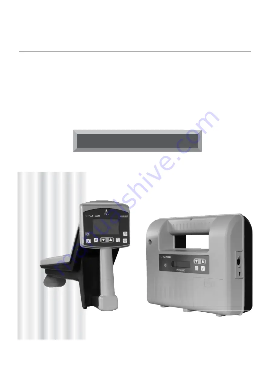
PL-G.MAX
Страница 1: ...OPERATION MANUAL FUJI PIPELINE AND CABLE LOCATOR PL G MAX ...
Страница 2: ... Maximum Bar Sonde Mode 24 5 2 2 Pipe Axis Display 26 5 2 3 Continuous Depth Measurement 27 5 2 4 Pull up Measurement 28 Bluetooth Depth Data Collection 29 5 2 5 Transverse Depth Measurement 30 5 2 6 Detection by Sonde 31 5 2 7 Radio Mode 32 5 2 8 AC CP Mode 33 6 OPERATION IN EACH SITE SITUATION 6 1 Detection by Induction Mode 6 1 1 With 2 surveyor 34 6 1 2 With 1 surveyor 36 6 2 Depth and current...
Страница 3: ...es and metallic water pipelines Thank you very much for purchasing the Fuji Tecom PL G MAX Pipeline Locator It is highly recommended that you read this instruction manual to ensure safe and effective operation of the locator This instruction manual will go over the many features of the Fuji Tecom PL G Max along with recommended approaches in locating pipes in different scenarios ...
Страница 4: ...ocations 13 Repeat steps 5 10 using locate tools additional frequencies by first changing the frequency on transmitter and then the receiver 14 The locate tool should be tagged and sent in for service and calibration if a change is identified in the following readings Test Results Any Location change in the X Y orientation or left or right over the test line the Receiver should consistently read a...
Страница 5: ...f any of the above problems occur ensure that the locate tool is tagged and sent in for service calibration Leaking Battery Procedure Whenever replacing batteries thoroughly examine dead or low batteries for evidence of leakage Look in battery compartments and look for evidence of residue Do not put new batteries in transmitter or receiver if any residue is observed In the event of leaking batteri...
Страница 6: ...ith your purchase Fuji Tecom takes all possible measures to ensure quality but if any of the components are missing please contact the store you bought your locator from immediately 1 Transmitter Unit 2 Receiver Unit 3 Ground Stake 30 cm 4 Warning Flag Direct Mode Cable 5 Direct Mode Cable 6 Soft Carrying Bag ...
Страница 7: ...ji Tecom PL G MAX Locator 1 External Induction Coil and Cable For locating energized power lines 2 External Coil Bar 3 External Power Supply Cable 4 Cable Drum with 50 meter cable For the Loop Cable Mode 5 Sonde Small Large 6 Headphone 7 Soft Carrying Bag with earth function ...
Страница 8: ...eration Panel Power Switch Key On Off Switch Loop Check Key pg 20 Frequency Selection Key Output Power Control Keys LCD Warning Flag Holder LCD Display Operation Panel Direct Mode Connector Access External Power Connector Access Battery Case Cover Access ...
Страница 9: ...Mode 83kHz or 27kHz or 8kHz or MIX MIX means the simultaneous output of 83kHz 27kHz and 8kHz Output Mode Display IND Induction Mode DIR Direct Mode Displays power source shown as Internal D Size Residual Battery Condition External 12 volt Power Supply Output Level in 8 steps from 0 to 7 Output Power Condition in the Direct Mode Output Power Supply Value 0 00 to 999 mA The transmitter has an Auto O...
Страница 10: ...tery indication displayed on the LCD is reduced to Zero replace ALL batteries How to change the batteries NOTE Confirm the polarity of battery when the batteries are mounted in the Battery Case The residual power is indicated on the LCD OK Change batteries ...
Страница 11: ...djustment Key Depth Measurement Key Back Light Key Sound Volume Control Key Adjust speaker volume with short presses Turn vibrations ON or OFF with long presses LCD LED Headphone Plug Connector Located at the back side of Receiver LCD Operation Panel Handle to operate Battery Case Cover Antenna Headphone Plug Connector Speaker Foot Plate ...
Страница 12: ...lected exploration method Maximum Mode Continuous Depth Mode Bar Antenna Mode Sonde Mode Ⓒ Sensitivity Level transmitted from the Transmitter 00 40 Ⓓ Battery level display Ⓔ Vibration on off ON OFF Ⓕ Speaker volume level Low High Ⓖ Pipe direction Ⓖ Ⓐ Ⓔ Ⓕ Ⓒ Ⓓ 27kHz S21 048 ...
Страница 13: ...ing Quantity Maximum Mode Display Maximum Mode Display Pipe Direction Level Value Bar Graph Bar Antenna Mode Display Bar Antenna Mode Display BAR Sonde Mode Display Sonde Mode Display Continuous Depth Display Continuous Depth Display Current Index Value 0 100 Received Level 2 3m Depth 0 0 5 0m 51 72 ...
Страница 14: ...is not available in BAR Mode How to check Current Index Value Display shows the current value of the pipeline detected by the Receiver Transverse Depth Display pg 30 3 5m Current Index Value 0 100 Depth 0 0 5 0m Pull Up Depth Display 000 051 Level Value Marker ...
Страница 15: ...y icon on the LCD display is reduced to Zero as shown please replace all batteries How to change the batteries NOTE When the Battery indication reduces to Zero the Receiver Turns OFF automatically The residual power is indicated on the LCD OK Change batteries ...
Страница 16: ...ng through the ground at relatively low frequencies This detector utilizes this property A current is generated in a pipe by a transmitter and a magnetic field is generated by the induced current This detector picks up the magnetic field by a receiver to detect a buried pipe Magnetic Field Transmitter Receiver Pipeline Magnetic Field Inducted current ...
Страница 17: ... target pipe and the transmitter with a cable and apply the electric current directly to the pipeline and generate a mag netic field that can be detected by the receiver Induction Mode A magnetic field is generated by the transmitter and an electric current is generated in the pipeline from the magnetic field and simultaneously secondary magnetic field is generated to be detected by the receiver I...
Страница 18: ...ltaneous output 83kHz 27kHz 8kHz POINT Use the MIX Mode to select the best frequency POINT When in the Mix Mode the Transmitter operates at a lower output Induction Mode Appropriate selection of frequency 83kHz The default frequency for ordinary pipeline detection and congested areas with multiple utilities 27kHz for Long distance single pipeline tracking Select this frequency if the fluctuation o...
Страница 19: ... the Transmitter on during use the Transmitter will stay ON until the batteries are depleted The following are instructions on how to enable CONTINUOUS with the mages on the left acting as guides 1 Turn off the Transmitter 2 Hold down the Frequency key 3 Turn on the Transmitter While still holding down Frequency 4 The Transmitter LCD screen should display CONTINUOUS and the tool is now functioning...
Страница 20: ...er X Y detection above the pipeline 83kHz is most commonly used It is useful for congested areas and pipelines of a shorter distance This produces a clear tight X Y orientation above the pipeline 8kHz is used only in the IDT mode useful for locating tracer cables and branch pipelines MIX is the simultaneous output mode of 27kHz 83kHz and 8kHz 5 Set the Output Level with the Key as shown 6 Confirm ...
Страница 21: ...r orientation of the Transmitter is helpful in producing the best results Keep the Transmitter at a right angle to the pipeline and keep the Ground Stake a good distance away from the pipeline where possible Refer to the image to the left ...
Страница 22: ...sy to check the connection state with the pipe 2 The smaller the value of the terminal impedance 1 Ω or less the better the connection state of the loop to be located Also the smaller the phase difference phase angle of the signal returned the better the connection state becomes 15 or less 3 If the impedance value is high there is a high possibility another pipe or insulated joint is interfering s...
Страница 23: ...Branch Pipelines Power Cables and Telephone Cables 2 Clamp the External Coil on the pipeline or cable as shown by the above figure Note To avoid electric shock wear rubber gloves while the External Coil is clamped on the power cable wear 3 The Transmitter is operated in the same way as the Direct Mode 83kHz is used for the External Coil Mode External Coil Transmitter Pipeline ...
Страница 24: ...2 Choose the frequency of 83kHz or 27kHz 27kHz is useful for locating straight and long pipelines 83kHz is useful for locating pipelines of a shorter distance and for locating pipelines in con gested areas Choose the frequency in accordance with the condition on site The default frequency of 83kHz is automatically selected when the Transmitter turns on The frequency of 8kHz can be used with the Di...
Страница 25: ...ht switch to illuminate the LCD display Point 3 Press the volume switch until the volume is appropriate for operation Large Medium Small OFF The vibration function is turned ON OFF by long press Pull Up Horizontal Maximum Mode It is useful to locate the position of pipeline correctly Minimum Mode It is used to go faster by locating the pipeline roughly Bar Mode It is utilized to locate the pipelin...
Страница 26: ...d Low 080 Speaker Sound High 020 Speaker Sound Low Right on the buried pipe Location of pipeline or cable Location of pipeline is indicated as the point where the peak of the bar graph in the panel display is the maximum Point In the event the bar graph scale swings widely it is possible that some pipelines are buried closely Refer to page 38 section 6 3 ...
Страница 27: ...R Motion of LED Vibrator 040 070 080 070 040 040 070 080 070 Explanation LED Vibrator operation can be turned ON OFF by holding down the key for a long time Pipeline Pipeline LED Light Off LED Light On Vibrator OFF Vibrator ON ...
Страница 28: ...The correct direction may not be shown on parallel pipes and bent pipes The direction of the receiver and the pipeline are the same The direction of the receiver is somewhat different from the di rection of the pipe The direction of the receiver is offset by 45 degrees from the direction of the pipe The direction of the receiver is almost offset by 90 degrees from the direction of the pipe The dir...
Страница 29: ...is in the correct mode when this icon is displayed Then place the receiver on ground level above the pipelines Step 3 Slowly walk along the presumed pipeline while carrying the receiver as close to the ground surface as possible This will help generate accurate depth readings Ensure you also maintain correct orientation while walking as shown in the diagram to the bottom left NOTE Pressing the dep...
Страница 30: ...itch NOTE depth cannot be measured with Bar mode When you see PULL UP on the LCD screen fully pull Up extend the antenna After pulling up completely the measured value will be displayed on the LCD screen Attention Do not move the antenna after pressing the depth measurement key until PULL UP appears on the display Do not move the antenna after pulling up the antenna until the depth result is displ...
Страница 31: ...wn the Depth button on the PL G until it says Wait Connection 4 Quickly on your Android device turn your Bluetooth on and connect to PL G MAX as soon as it appears If prompted confirm the connection by selecting PAIR or OK 5 Quickly find and open the PL AP app and select PL G 6 Quickly Select the Data Transfer button This button should then turn into a Stop Transfer button 7 The PL G receiver will...
Страница 32: ...where the marker and bar graph align The buzzer should also be audible 6 Repeat the process on the other side of the pipeline The total distance equals the depth This method is suitable for depths of 0 5 2 0 meters To return to the MAX PEAK mode press the Sensitivity Adjustment key OPERATION OF RECEIVER 5 2 5 Transverse Depth Measurement 27kHz S21 Transvers depth measurement screen LED Lighting 03...
Страница 33: ... Key 1 and check the battery power dis played on the LCD 2 Choose Sonde Mode with the Mode Selection Key 3 See page 24 to learn about Sonde NOTE The Receiver must be oriented parallel to the pipeline as shown by the figure to the left The Receiver should move in the direction of the arrows in accordance with the movement of Sonde as shown in the figures NOTE The Transmitter is not used in Sonde Mo...
Страница 34: ...nduced onto the pipeline 1 Push the Frequency Selection Key 2 and choose the Radio Mode displayed on the LCD screen 2 Select MAXIMUM PEAK Mode with the Mode Selection Key 3 3 Adjust the sensitivity with the Sensitivity Adjustment Key 4 NOTE The depth of a pipeline cannot be measured when in RADIO Mode Use MAXIMUM Mode to measure the depth of a pipeline ...
Страница 35: ...r key and confirm that there is enough battery remaining to operate the receiver 2 Push the Frequency Selection Key and choose the Live Cable Mode as displayed on the LCD screen 3 Select Maximum Mode or Bar Mode with the Mode Selection Key Use Maximum mode initially for sharp peak indication of cables Sensitivity increases with bar mode but peak indication over cable is wider ...
Страница 36: ...ver to Maximum Peak Mode Change the output level of the transmitter to 2 5 Output level will vary for different sites Search for a position where the receiver s bar graph and numerical value reaches a maximum while moving the transmitter and receiver sideways as shown in the diagram below Adjust the sensitivity of the receiver to a level that is easy to distinguish Maintain a constant distance bet...
Страница 37: ... receiver Since maximum allowed distance between the transmitter and buried pipeline is approx 2 m make sure to select the detecting position 030 080 2m from Pipe is the limit Over 2 m Adjust direction of the transmitter is perpendicular to direction of the pipe Variation of Bar graph Level numeric value POINT 1 POINT 3 POINT 2 POINT 1 POINT 2 POINT 3 20 20 80 Installation Advice Ex 1 distance fro...
Страница 38: ...sen in accordance with site conditions Place the Transmitter on the ground where the pipeline is presumed to be buried Turn on the Receiver and select the same frequency as the Transmitter 83kHz or 27kHz Have approximately 5 meters or more between the Transmitter and the Receiver The Transmitter is must face the Receiver as shown by the figure on the left Locate the point where the Receiver displa...
Страница 39: ... differentiating pipelines that are in close proximity to each other The placement of the Transmitter and the depth of each pipeline will determine the current response of each pipeline being located As the operator tracks the pipeline away from the transmitter the current response decreases It is common for each pipeline to have a different current response in relation to each other Observing the...
Страница 40: ...ver to pipeline B approximately 2 meters off pipeline B 4 Locate pipeline A and B Depending on field conditions the line indications may be slightly distorted 5 Place the transmitter above each pipeline and take depths Compare the depths gathered as shown in the diagram below Detection by Induction Mode As shown in Fig 1 it is confirmed that the buried pipe is in parallel because the maximum sensi...
Страница 41: ...se Direct mode as much as possible if there are parallel pipes The diagram below shows what to expect in this setting Using exposed parts of each parallel pipeline grounding closely to a pipeline will aid in detecting other pipes one by one Grounding position 030 080 030 ...
Страница 42: ...terpreting the depth shape of a pipeline when there are sudden changes in pipeline depth as shown in the first diagram below When using the continuous depth mode the pipeline depth is measured in certain intervals with the measurement depth displayed as shown in the second diagram below This mode makes it easier to accurately confirm the depth situation of the pipeline This mode is also useful whe...
Страница 43: ... 1 While using the receiver in the direction of the arrows the receiver will be most sensitive When passing through Point the bar graph will decreases sharply 2 Find the maximum point of the sensitivity by moving the receiver in a circular motion In the direction of Ⓒ and Ⓑ to find where the sensitivity decreases 3 Find the maximum point in sensitivity around and plot and to help find the bend at ...
Страница 44: ...round is such that the ground is grounded on the right side for detecting the branch pipe on the right side Set the frequency to 83 kHz 2 As shown in the figure the receiving antenna moves about 1 m away from the main pipe in parallel with the direction of the thick arrows and looks for the maximum sensitivity point Ground location 030 030 080 ...
Страница 45: ...e or curb as shown in the diagram below Operation of receiver If crash barriers curbstones etc are located close to the pipeline these effects will be noticed on the receiver On such a site please perform the detection next to the guard fence or the curb as shown above Road Transmitter barrier Guard fence Pipeline Blank of Guard fence Bar graph Sensitivity curve receiver response Pipeline Guard fe...
Страница 46: ...her the buried depth becomes unclear In such a site please detect with an external induction coil for pipeline inspection CAUTION It is impossible to detect the depth of a single buried pipe in places where there are multiple tightly packed pipelines such as the ones shown in the diagram Bar graph Sensitivity curve receiver response ...
Страница 47: ...e of high voltage lines and substation equipment as shown in the diagram to the left Detect the pipelines from both areas You may then assume the pipeline s shape and direction in between the two points 6 11 When detecting near buildings When a pipeline is buried near buildings the position and depth may become unclear due to the interference of steel structures etc In such a case use the direct m...
Страница 48: ...ve to the location where the receiver signal becomes stable In order to perform more accurate detections it is recommended to detect using Direct mode with or without an external magnetic coil 6 13 When there are nearby railways In the event the pipeline is next to a railway track the tracks and fences may cause signal interference In such a case please use a transmitter on the outside of the fenc...
Страница 49: ... pipeline When the pipeline is in a factory 6 16 When there are reinforcement bars in the pavement There may be cases in which rebar is in the pavement such as in gas stations or a factory where a large vehicle enter This makes locating and depth measurement of a pipe impossible ...
Страница 50: ... is turned on b Confirm that both the Receiver and Transmitter are operating on the same frequency 3 When the sensitivity readings of the Receiver is weak a The farther the transmitter is from the receiver the weaker the signal from the transmitter is A weak signal affects the measurement of depths Move the transmitter closer to the Receiver b Do not set up the Transmitter on iron surfaces such as...
Страница 51: ...icates Power OFF after one hour of idling or if the tool was turned off 2 Receiver displays indicates the signal strength is too high indicates that the Antenna is not pushed down completely indicates the depth of a pipeline could not be measured indicates the depth measurement cannot be taken in this mode of operation indicates the signal is too weak from the Transmitter indicates an unstable sig...
Страница 52: ...h detection Pull Up Type Depth 1 2 m Within 5 Depth 2 0 m Within 5 Depth 5 0 m Within 10 Measurable depth range 0 m to 5 m Transverse type Effective depth range 0 5 to 2 m 10 Continuous type Effective depth range 0 to 2 m 20 According to the test and test conditions of our company s technical development center Usage in Direct mode D I R ...
Страница 53: ...quency 83kHz 27kHz 8kHz Radio Mode 15kHz 25kHz AC CP Mode 50 60Hz Level Change Display Bar graph and pitch change in the liquid crystal screen Display of reception level 3 digit number display Depth measure 3 digit number display on liquid crystal screen 2 digit display at continuous depth measurement Current measure 3 digit number value on LCD screen Power supply DC9V AA size batteries x 6 LR6 Dr...
Страница 54: ...p Cord reel connecting cable length 50 cm Weight 0 65 kg complete set Large alligator clip Applicable tube diameter maximum φ 100 mm Size Width 167 mm Thickness 33 mm Length 174 mm Weight 0 38 kg Outer magnetic coil option Outer magnet coil body Applicable frequency 8 kHz to 334 kHz Applicable tube diameter Outside diameter φ 100 mm or less Size Width 184 mm Thickness 29 mm Length 206 mm Weight 0 ...
Страница 55: ...nce services are needed If your PL G MAX Locator is malfunctioning during ordinary use or handling you can have it repaired free of charge within the warranty period Please send the malfunctioned PL G MAX Locator to a FUJI distributor within the warranty period and identify the defective condition s in detail After the warranty period we or our distributor will require the expense incurred in repa...