FinePix A310 Service Manual
2. Disassembly
13
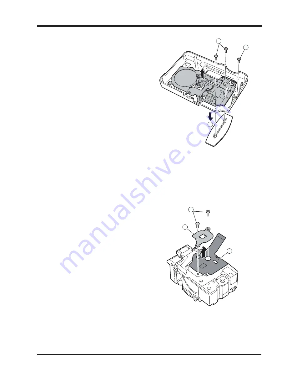
2-9. Removing the LINK Assy
[Disassembly]
1. Remove two screws (M1.7x3.5). andRemove the
Grip parts in the direction of the arrow.
2. Remove the screw(M1.7x3.5).
3. Remove the LINK Assy in the direction of the arrow.
1
1
2
3
[Assembly]
Assemble in the reverse order to disassembly.
2-10. Removing CCD PWB Assy
[Disassembly]
1. Remove two screws (M1.7x3.0). and
2. Remove the CCD PLATE .
3. Remove the CCD PWB Assy in the direction of the
arrow.
[Assembly]
Assemble in the reverse order to disassembly.
1
2
3
Содержание FinePix A310 AS
Страница 19: ...19 FinePix A310 Service Manual 3 Schematics 3 8 CAMERA BLOCK Schematic Diagram...
Страница 20: ...20 FinePix A310 Service Manual 3 Schematics 3 9 PROCESS BLOCK Schematic Diagram...
Страница 21: ...21 FinePix A310 Service Manual 3 Schematics 3 10 POWER BLOCK Schematic Diagram...
Страница 22: ...22 FinePix A310 Service Manual 3 Schematics 3 11 VIDEO BLOCK Schematic Diagram...
Страница 23: ...23 FinePix A310 Service Manual 3 Schematics 3 12 KEY IC BLOCK Schematic Diagram...
Страница 25: ...25 FinePix A310 Service Manual 3 Schematics 3 15 MOTOR BLOCK Schematic Diagram...
Страница 26: ...26 FinePix A310 Service Manual 3 Schematics 3 16 LCD BLOCK Schematic Diagram...
Страница 27: ...27 FinePix A310 Service Manual 3 Schematics 3 17 FLASH BLOCK Schematic Diagram...
Страница 74: ...26 30 Nishiazabu 2 chome Minato ku Tokyo 106 8620 Japan FUJI PHOTO FILM CO LTD...


