Chapter 4: Wiring
_______________________________________________________________________________________________________________
14
4.3 Wiring for control circuit terminals
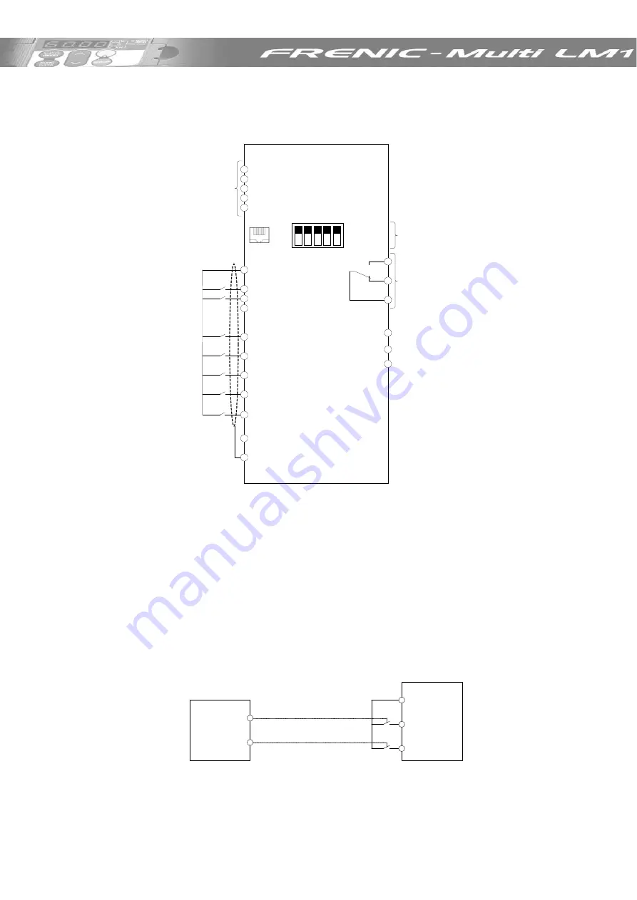
The diagram below shows a basic connection example for running the inverter with terminal
commands.
Figure 4.7 Control terminal connexions
4.4 Control terminals description
a. Analog inputs
Using analog inputs the motor speed can be set without steps (stageless).
b. Digital Inputs
The digital inputs can operate using NPN or PNP logic. The selection of the logic is set using
slide switch SW1 located on the control PCB.
Factory setting is PNP (Source) Logic.
Connection example using PNP Logic:
Lift controller
FRENIC-Multi LM1
Up
Speed 1
X1
FWD
PLC (+24 V)
Figure 4.8: Normal connection using free potential contacts of the lift controller.
12
11
V2
C1
11
PLC
FWD
REV
CM
X1
X2
X3
X4
X5
CM
Y1
Y2
CMY
FRENIC-Multi LM1
30A
30B
30C
Analog Inputs
Keypad connector or
RS 485 (Modbus RTU)
Up
Down
Lift direction:
X1 to X3: Binary
combination inputs for
speed set points selection
(see Table 6.2)
Coast to stop
(Inverter enable)
Common 0V
Voltage power 24 VDC
Slide switches on the
control board for
hardware configuration
Relay output
for any alarm
Brake control signal
Motor contactors control signal
Common for transistor outputs
GND
Rescue operation
(BATRY)


