4
This pump is designed to accept an o-ring on the discharge
flange and inlet chamfer as a backup to the NPT or BSP
threads to ensure leak-free operation after temperature
cycling.
After verifying the setting and setscrews tension on the
drive magnet assembly, grip the pump end by the dis-
charge and the opposing front edge of the motor adapter
and install the pump end on to the motor. Secure to the
motor with correct hardware (items 10A, 10B, and 10C).
CAUTION
: Do not allow fingers between the motor face
and the motor adapter.
2. For metric pumps - Follow assembly instructions for metric
pumps on page 1, steps 3 through 10.
Note:
Plastic pumps will expand and contract with tem-
perature, so periodically check and hand tighten screws.
BUSHING REPLACEMENT
1. To remove the bushing, insert a 1/16” pin punch into bal-
ance hole (inner circle of 4 holes) of impeller assembly
(items 2 & 3). Gently tap the bushing out of the back of the
impeller assembly. The punch may need to be moved to
a different hole if the bushing is difficult to remove.
2. To replace the bushing, clean the impeller bore. Insert
the new bushing into the back of the impeller assembly
by aligning the bushing with the impeller bore. Press
gently until the bushing bottoms out (use a block of wood
and mallet if necessary).
REASSEMBLY
1. 56C pumps - Insert the barrier (item 4) into the motor
adapter (item 5). Align the barrier tabs with the motor
adapter bolt holes and press/pop into place. Install the
impeller assembly (items 2 and 3) into the barrier. Lubricate
the housing o-ring (item 7) with a chemically compatible
lubricant and install. Carefully place the impeller housing
(item 1) onto the barrier, lining up the discharge with a set
screw access hole (top) in the motor adapter. Be careful not
to dislodge the o-ring. Install the six bolts and washers
(items 9A, 9B, and 9C) and hand tighten the screws follow-
ing the pattern shown in figure 3.
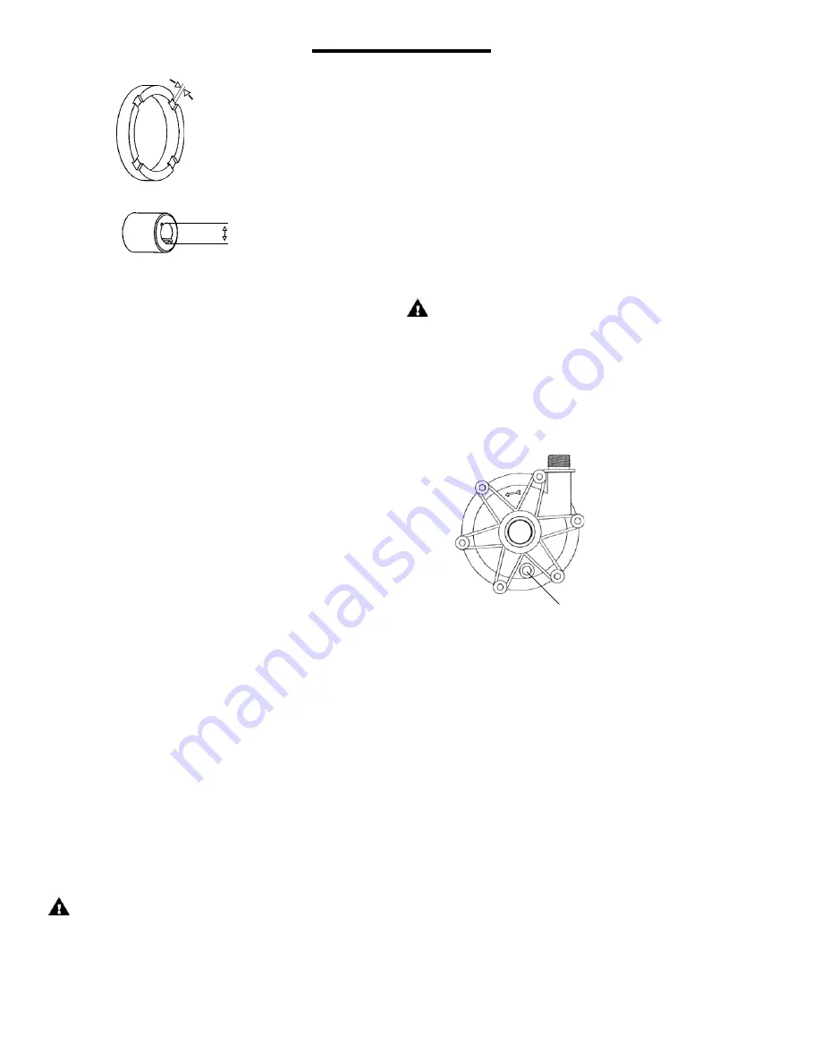
Figure 6
Drain fitting molded boss.
Use as a guide for drill ing
and tapping 1/4” NPT.
OPTIONAL DRAIN INSTALLATION SECTION
1. Remove the impeller housing from the pump assembly.
2. Clamp the impeller housing to a drill press table.
3. Using a 7/16” drill and the molded boss as a guide, drill
completely through the molded boss into the interior of
the impeller housing. De-burr the hole on the inside of
the impeller housing. See Figure 6.
CAUTION:
Do not tap too deep or the impeller housing
may be damaged.
4. Using a 1/4” NPT tap, tap the hole in the molded boss to
the appropriate depth.
5. Install drain plug or valve, being careful not to overtighten.
2. Check for loose magnets on drive assembly or rubbed
areas on impeller or barrier assemblies. Contact your
distributor or FTI Technical Service if a problem is found.
3. If you did not remove the drive magnet assembly, check
the set screws for tightness before reassembly.
Figure 5
.020” min
.
.415” max.
CAPABILITIES
Maximum working pressure: 60 psi (4 bar)
Содержание KC 10 Series
Страница 5: ...5 KC5 5 6 6H 7 8 10 EXPLODED VIEW ...
Страница 9: ...Service 800 888 3743 J102714 Rev 18 4 4 2019 ...


