


Page 26 of 28
Rev. A
10. Check if there is a battery voltage on regulator 7805 input.
11. Check Q11 (MPS2907A), Q12 (2222ASM) and replace them if abnormal.
12. Check there is + 12Vdc on 7805 input.
13. Replace abnormal Q11.
14. Check there is + 5Vdc on U03 (7805)
15. Replace abnormal 7805.
16. Replace PCB
17. Check if buzzer beeps and LED extinguished.
18. Check if battery voltage is correct.
19. Replace abnormal batteries.
20. Check if R17A is normal.
21. Replace abnormal R17A.
22. Replace PCB.
23. Buzzer beeps and LED flash.
24. Check if fault LED lights and buzzer beeps continuously.
25. Check if CPU is shorted.
26. Replace abnormal CPU.
27. Check if the value of R83/ / R82(or R63/ / R86) is correct.
28. Replace R83/ / R82 (or R63/ / R86).
29. Check if Q4, Q9, Q19 (or Q30, Q29 Q15) are ok.
30. Replace Q4, Q9, Q19 (or Q30, Q29 Q15).
31. Replace PCB.
13.7.2
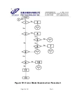
Line mode examination ( please refer to flow chart Figure W- 8)
I f battery mode examination is OK, then do the line mode examination as
below.
1. Plug in input power cord at right voltage range. Check if main relay RY01 is
active.
2. Replace main relay.
3. Check if full-bridge rectifier is short.
4. Replace abnormal diode
5. Check Q14 (2222ASM collector) if there is zero crossing signal.
6. Replace abnormal Q14. Check if UPS remains on line mode.
7. Replace PCB.
8. Check if buzzer beeps continuously and fault LED lights.
9. Check if Buck/ Boost relays (RY02, RY03) are bad.
10. Replace abnormal Buck/ Boost relays (RY02, RY03).
11. Replace PCB.
Содержание 1500 Series
Страница 2: ...Page 1 of 28 Rev A UNINTERRUPTIBLE POWER SYSTEM SPECIFICATION EP 1000 1500 2000 Series ...
Страница 3: ...Page 2 of 28 Rev A 1 0 Revision Summary REVI SI ON SECTI ON DESCRI PTI ON Rev A Formal Release ...
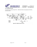
Страница 9: ...Page 8 of 28 Rev A Figure S 2 Control Power Circuit CH1 C15 å GND Figure W 1 Cold Start ...
Страница 11: ...Page 10 of 28 Rev A Figure S 3 B Charger Control Circuit ...
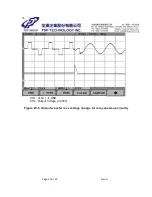
Страница 16: ...Page 15 of 28 Rev A CH1 DS N CH2 Output Voltage 1 200V Figure W 3 Control logic 1 ...
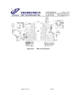
Страница 19: ...Page 18 of 28 Rev A Figure S 6 CPU Control Circuit ...
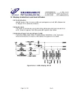
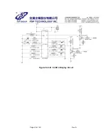
Страница 23: ...Page 22 of 28 Rev A Figure S 8 B 6 LEDs Display Circuit ...
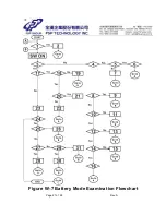
Страница 28: ...Page 27 of 28 Rev A Figure W 7 Battery Mode Examination Flowchart ...
Страница 29: ...Page 28 of 28 Rev A Figure W 8 Line Mode Examination Flowchart ...


