


Page 25 of 28
Rev. A
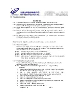
13 Troubleshooting
WARNI NG
13.1 Troubleshooting can be done by qualified engineer or technician only.
13.2 Use isolated AC source for your oscilloscope to prevent floating voltage problem
between UPS chassis ground and system reference ground.
13.3 Before opening the cover, turn off the main switch and unplug the input power
cord.
13.4 Because hazardous voltage may remain in the DC capacitors, wait for at least 5
minutes after turning off the UPS and disconnecting the power cord before open its
cover.
13.5 Do NOT plug in the input power cord before you reconnect the connectors
of battery to prevent unwanted sparks.
Please follow the steps below when you want to repair a problematic unit:
13.6 Visual inspection
This is the first step to check the UPS after opening its cover. Be sure to do the
visual inspection because it can help you to identify most problems. Major items
that should be checked are listed below:
13.6.1
Are there any connectors or terminals loose?
13.6.2
Are there any components burn-out or discolored?
13.6.3
Especially the power components on the heat sink?
13.6.4
Are there any capacitors broken or leakage? Check all the components
listed above and replace which is abnormal.
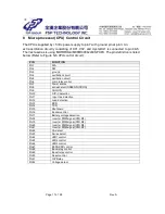
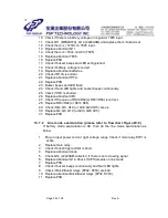
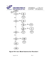
13.7 Troubleshooting flow chart
To prevent from hurting yourself and damaging the UPS, be sure to obey the
sequences of flowchart listed below.
13.7.1
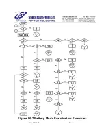
Battery mode examination ( please refer to Figure W- 7)
Procedure:
1. Replace batteries by DC power supply and turn on it. Check if there is current
limit phenomenon for DC power supply.
2. One or more MOSFETs (Q5, Q6~ 8) is D-S short. Check
and replace it. I f MOSFETs have been replaced once, replace the PCB.
3. Check if both buzzer beeps and LED flash for once.
4. Check if + 5Vdc on CPU pin 7 is normal.
5. Check if clock signals on CPU pin4 and 5 are correct.
6. Replace the CPU. But if the CPU has been replaced once, replace the PCB.
7. Replace abnormal crystal XL1.
8. Check if Q18, Q21, Q22 and Q23 are OK.
9. Replace abnormal Q18, Q21, Q22 and Q23.
Содержание 1500 Series
Страница 2: ...Page 1 of 28 Rev A UNINTERRUPTIBLE POWER SYSTEM SPECIFICATION EP 1000 1500 2000 Series ...
Страница 3: ...Page 2 of 28 Rev A 1 0 Revision Summary REVI SI ON SECTI ON DESCRI PTI ON Rev A Formal Release ...
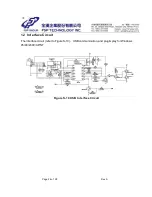
Страница 9: ...Page 8 of 28 Rev A Figure S 2 Control Power Circuit CH1 C15 å GND Figure W 1 Cold Start ...
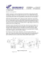
Страница 11: ...Page 10 of 28 Rev A Figure S 3 B Charger Control Circuit ...
Страница 16: ...Page 15 of 28 Rev A CH1 DS N CH2 Output Voltage 1 200V Figure W 3 Control logic 1 ...
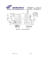
Страница 19: ...Page 18 of 28 Rev A Figure S 6 CPU Control Circuit ...
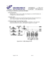
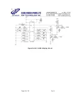
Страница 23: ...Page 22 of 28 Rev A Figure S 8 B 6 LEDs Display Circuit ...
Страница 28: ...Page 27 of 28 Rev A Figure W 7 Battery Mode Examination Flowchart ...
Страница 29: ...Page 28 of 28 Rev A Figure W 8 Line Mode Examination Flowchart ...


