


CAP881
25
B.
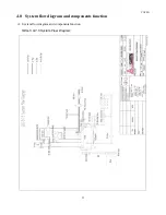
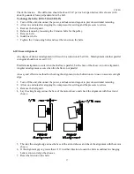
Description of system flow chart and component function
1. Air flow path (refer to the flow chart for each type)
1.1. After dust is removed by the intake filter, clean air goes through the air inlet valve into the
compression chamber and is mixed with oil. The mixture is compressed and delivered into the oil
receiver tank, Air/Oil Separator, minimum pressure valve, (and after cooler on SEG-10 & 15
models only).
1.2. Function of parts in the air flow path
(1). Air intake filter
Air intake filter is a suction filter which is a special-purpose air cleaner of the air compressor. For
normal environmental use, clean out the dust on the element every 2,000 hours of operation. Do
not use compressed air.
(2). Air Inlet Valve
On/Off Load Control
:
for SEG-5/SEG-7.5/SEG-10/SEG-15 models
The solenoid valve is switched by different capacity controls such as: start, stop, off load. Each
will move the piston of the intake valve. The minimum pressure valve (MPV) keeps minimum
pressure to maintain oil circulation.
When system pressure is less than the unload setting value, the solenoid valve is activated and the
air inlet valve opens fully. When the value is reached, the intake valve closes and the compressor is
then running off load.
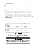
(3). Temperature Sensor
Lack of oil in circulation will induce high discharge temperature. It displays on the panel through
the signal from the thermal couple. General setting value is 212°F (100
℃)
. Do not operate the unit
over this temperature otherwise a trip will occur.
(4). Oil Receiver
There is a sight glass on the bottom side of the receiver. Maintain the oil level between H-L.
On the bottom there is a drain valve, remember to drain condensate water every time before
startup. In addition, an oil fill hole for oil replacement is on the tank as well.
The larger cross-section area design
of this tank will slow down the compressed air,
this is known as the first stage of air oil separation.
(5). Air/Oil Separator
Refer to the description on oil flow path.
(6). Solenoid Valve
During start, stop, or off load operation, this valve will release pressure to ensure the air end starts
without back pressure or stops under off load operation.
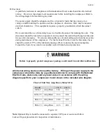
(7). Minimum Pressure Valve
Minimum pressure valve is located at the outlet air discharge from Air/Oil Fines Separator Tank.
Operating pressure is set at around 65 PSIG. The functions of minimum pressure valve are shown
below:
A. To build up oil circulation pressure and operating temperature at start.
B. When pressure is over 65 PSIG, it will reduce flow rate passing and protect air/oil separator
from damage due to large pressure difference and increase oil separator efficiency.
C. Prevent back flow under off load running.
(8). After Cooler (On SEG-10 & 15 Models Only)
The compressed air is circulated through the aftercooler which is cooled by the blower attached to
the main motor shaft. Generally discharge air temperature is 27°F above ambient temperature.
Environment is a crucial factor for air-cooled type air compressors. Install in a
well-ventilated area.
Содержание SEG-10
Страница 11: ...CAP881 11 ...
Страница 12: ...CAP881 12 ...
Страница 13: ...CAP881 ...
Страница 14: ...CAP881 14 ...
Страница 15: ...CAP881 ...
Страница 16: ...CAP881 16 ...
Страница 17: ...CAP881 17 ...
Страница 18: ...CAP881 18 ...
Страница 20: ...CAP881 20 ...
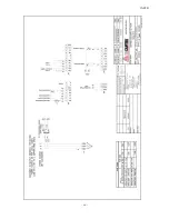
Страница 24: ...CAP881 24 SEG 10 15 System Flow Diagram ...
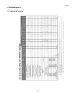
Страница 32: ...CAP881 32 6 0 Maintenance 6 1 Maintenance Intervals ...
Страница 44: ...CAP881 44 NOTES ...