1
Max. fault loading: 24V,1A
DC Input: 12-48V,1.25A max.
AC Input: 24V~,0.7A max.
2 3 4 5 6
V1+ V1
PWR1
V2+ V2
PWR2
Fault
1
Max. fault loading: 24V,1A
DC Input: 12-48V,1.25A max.
AC Input: 24V~,0.7A max.
2 3 4 5 6
V1+ V1
PWR1
V2+ V2
PWR2
Fault
1 2 3 4 5 6
V1+ V1
PWR1
V2
+
V2
PWR2
Fault
6
EN
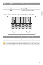
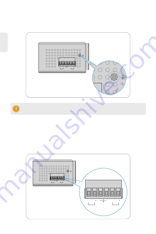
The Upper Panel of the switch indicates an AC/DC inlet power socket and consists of one terminal
block connector within 6 contacts. Please follow the steps below to insert the power wire.
1. Insert positive/negative AC or DC power wires into Contacts 1 and 2 for Power 1, or Contacts 5
and 6 for Power 2.
Connecting the Power
NOTE:
This product is intended to be mounted to a well-grounded mounting surface such
as a metal panel.
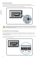
Grounding and wire routing help limit the effects of noise due to electromagnetic interference (EMI).
Run the ground connection from the ground screw to the grounding surface prior to connecting
devices.
Grounding the Switch
1
DC Input: 12-48V ,1.25A max.
AC Input: 24V~,0.7A max.
2 3 4 5 6
V1+ V1
PWR1
V2+ V2
PWR2
Fault
12-48VDC,24VAC


