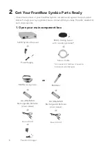
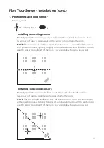
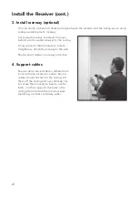
background image

14

Install the Ceiling Sensor (cont.) 

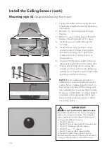
Mounting style #2: 

Suspended ceiling tile mount

1.   Locate the center of the ceiling tile and 

mark holes using the mounting bracket as 
a template.

2. 


 Drill  two 

1

/

8

”  mounting holes through  

the tile.

3.  

Drill a 

1

/

2

” sensor cable hole in line with 

the two mounting holes at 1 

1

/

4

” away.

4.  

  Insert the sensor cable through the  

1

/

2

” hole.

5.  

  Insert the two long machine screws  

(2 x M3 x 25mm Phillips) through the 
bracket and ceiling tile. Tighten the 
screws into rear of ceiling sensor, as 
shown above.

6.  

  Connect the IR sensor cable to the ceil-

ing sensor pigtail above the ceiling tiles.

7.  

  Route sensor cable above ceiling tiles 

toward your receiver location, following 
guidelines in chapter 4 and all applicable 
building and electrical codes.

2 x 

1

/

8

” holes

1

/

2

” hole

1

/

4

1

2

3

4

5

6

NOTE:

 Ensure cables are installed in 

adherence to local and national electric 
codes. Sensor cables should not rest on 
the ceiling. Lift them off the ceiling and 
use cable/zip ties to secure them loosely 
to beams, anchor bolts, or other support 
structures in the ceiling (do not attach 
them to duct work, plumbing, or other 
secondary work).

    IMPORTANT!


DO NOT ALTER THE IR SENSOR CABLE

Read the FrontRow Installer Guide thoroughly 
before installing sensor cable. The cable has 
been rigorously tested and qualified to work 
with your FrontRow IR sensors.
•  Do NOT shorten
•  Do NOT alter or replace the RCA connectors
•  Do NOT "splice" or split the cable
•  Do NOT use a "Y" adaptor 
•  Do NOT use any other type of cable
Altering the cable in any way will result in 
decreased performance of your system and will 
void your Manufacturer's Limited Warranty.

!

Содержание symbio 5201R

Страница 1: ...INSTALLER GUIDE 5201R Receiver symbio...

Страница 2: ...Parts Ready 6 7 Chapter 3 Get Yourself Ready 8 Chapter 4 Plan Your Sensor Installation 9 12 Chapter 5 Installing Sensors 13 16 Chapter 6 Install the Receiver 17 20 Chapter 7 Adjust the Amplifier 21 C...

Страница 3: ...used unless absolutely necessary Use of improper extension cord could result in a risk of fire and electric shock The cord MUST be plugged into a grounded outlet Make sure it is properly wired in goo...

Страница 4: ...2 Receiver Components Receiver 1 Receiver 2 Infrared ceiling sensor 3 Receiver power supply 4 Receiver mounting tray optional 1 4 2 3 Not necessary if FrontRow IR speakers are already installed...

Страница 5: ...g any electrical equipment Does your system meet the classroom requirements Check the table below to confirm that your classroom is set up properly for the FrontRow Symbio system you have In most case...

Страница 6: ...e area where students are sitting not the entire room Avoid installing speakers directly in front of the white board this not only covers an area not used by students but increases the chance of feedb...

Страница 7: ...x 13cm to solidly mount the wall bracket Avoid installing speakers directly in front of the white board this not only covers an area not used by students but increases the chance of feedback Correct...

Страница 8: ...e parts needed for each step separate 1 Open your main component box 940TM microphone AA LR6 NiMH Rechargeable Batteries silver sleeve Aux in Cord 5201R Symbio Receiver Not needed if FrontRow IR speak...

Страница 9: ...Kit for use with ezRoom Adapter Cable RJ45 RJ45 Adapter UTP CAT 5e Cable Volume Setting Label When using Symbio with ezRoom setup turn both volume controls to maximum setting Please DO NOT change thes...

Страница 10: ...tools Drill Wall anchors Drill bits Cable tacks staples Phillips 2 driver bit Plastic cable zip ties Level or ruler tape measure Plastic raceway with screws Crimp pliers or scissors Tin snips optiona...

Страница 11: ...in 15cm between the two whenever possible h Local regulations may require plenum rated cable if used in a plenum space Sensor cable supplied with your system is plenum rated 4 Plan Your Sensor Instal...

Страница 12: ...The windows allow the infrared light to escape from the classroom only to be picked up by the sensors in the adjacent classroom causing interference and cross talk Be sure to recommend window covering...

Страница 13: ...rom all parts of the room you ve probably chosen a good spot 1 Positioning a ceiling sensor Sensor symbols ceiling sensor Plan Your Sensor Installation cont Installing two ceiling sensors Mentally div...

Страница 14: ...nsor as shown below One near the back corner one near the front corner The sensors should be positioned on the side walls relative to whiteboard main lecture area at right angles to the board Be sure...

Страница 15: ...d in adherence to local and national electric codes Sensor cables should not rest on the ceiling Lift them off the ceiling and use cable zip ties to secure them loosely to beams anchor bolts or other...

Страница 16: ...all applicable building and electrical codes 2 x 1 8 holes 1 2 hole 11 4 1 2 3 4 5 6 NOTE Ensure cables are installed in adherence to local and national electric codes Sensor cables should not rest o...

Страница 17: ...he sensor 8 Route sensor cable along ceiling toward your receiver location following guidelines in chapter 4 and all applicable building and electrical codes 2 3 5 6 NOTE Ensure cables are installed i...

Страница 18: ...the center of the section of the room it s serving see chapter 4 3 Slide bracket onto the back of the sensor 4 Attach the sensor to the cable leading to the receiver 5 Press the bracket onto the wall...

Страница 19: ...and plug into power outlet DO NOT bundle the FrontRow power supply or any power supply along with the sensor cable DO NOT place the FrontRow power supply or any power supply directly next to or on to...

Страница 20: ...s a schematic illustration intended to clarify the relationship of components to each other The locationof jacks shown here may not reflect their true position on specific devices Symbio Wireless Mic...

Страница 21: ...er cable Power cable Sensor cable Adapter cable NOTE This is a schematic illustration intended to clarify the relationship of components to each other The locationof jacks shown here may not reflect t...

Страница 22: ...re to ensure straightness attach the raceway to the wall Route sensor cables in raceway and close 4 Support cables Ensure cables are installed in adherance to local and national electric codes Sensor...

Страница 23: ...l is active setting 8 recommended Set Mic Restore time the amount of time the amplifier waits between the end of an active microphone signal and resetting the other channels to their nor mal volume le...

Страница 24: ...It s difficult to assess your own voice 3 Try to find any areas where the receiver is not picking up your signal see Troubleshooting section on page 23 4 Try to find any areas where you experience ac...

Страница 25: ...l Size WxHxD 14 x 3 8 x 18 cm 5 5 x 1 5 x 7 in Weight 766g 1 7lbs Pendant Mic Transmitter 940TM Transmitting frequency 2 3MHz 2 8MHz switchable Transmission type Infrared Operating range 18 5m 60ft li...

Страница 26: ...ain direction install an additional sensor in that area of the room see pages 9 13 If using more than one microphone verify that they are not on the same channel Recharge or replace the microphone bat...

Страница 27: ...g could void the user s authority to operate those elements of the system IC notes This Class B digital apparatus complies with Canadian ICES 003 Cet appareil num rique de la classe B est conforme la...

Страница 28: ...14 USA Global Canada Australia Scandinavia 1690 Corporate Circle 6950 Creditview Road 629 Nudgee Road Kongebakken 9 Petaluma CA 94954 6712 Unit 1 Nundah QLD 4012 2765 Sm rum United States Mississauga...

Отзывы: