FrontLine FTS4USB Скачать руководство пользователя страница 7


P a g e

 | 

5


Connecting the USB ComProbe II to the Device Under Test (DUT) 

Once you have the software and the drivers loaded, the next step is to connect your hardware.  
The USB ComProbe II is a high speed, full speed and low speed USB 2.0 protocol analyzer that sends data 
using a high speed USB 2.0 connection. The recommended configuration requires two computers, one 
for communicating with the device under test and the other for displaying the results of the analysis. 

Although the USB ComProbe II can download analyzed data on a full speed USB 1.1 
connection, it is strongly recommended that you connect it using a high speed USB 2.0 
port to obtain optimal performance. If you experience any trouble with your analyzer, 
please ensure it is connected on a high speed USB 2.0 enabled host controller before 
contacting our technical support. 

Connecting only one Device Under Test 

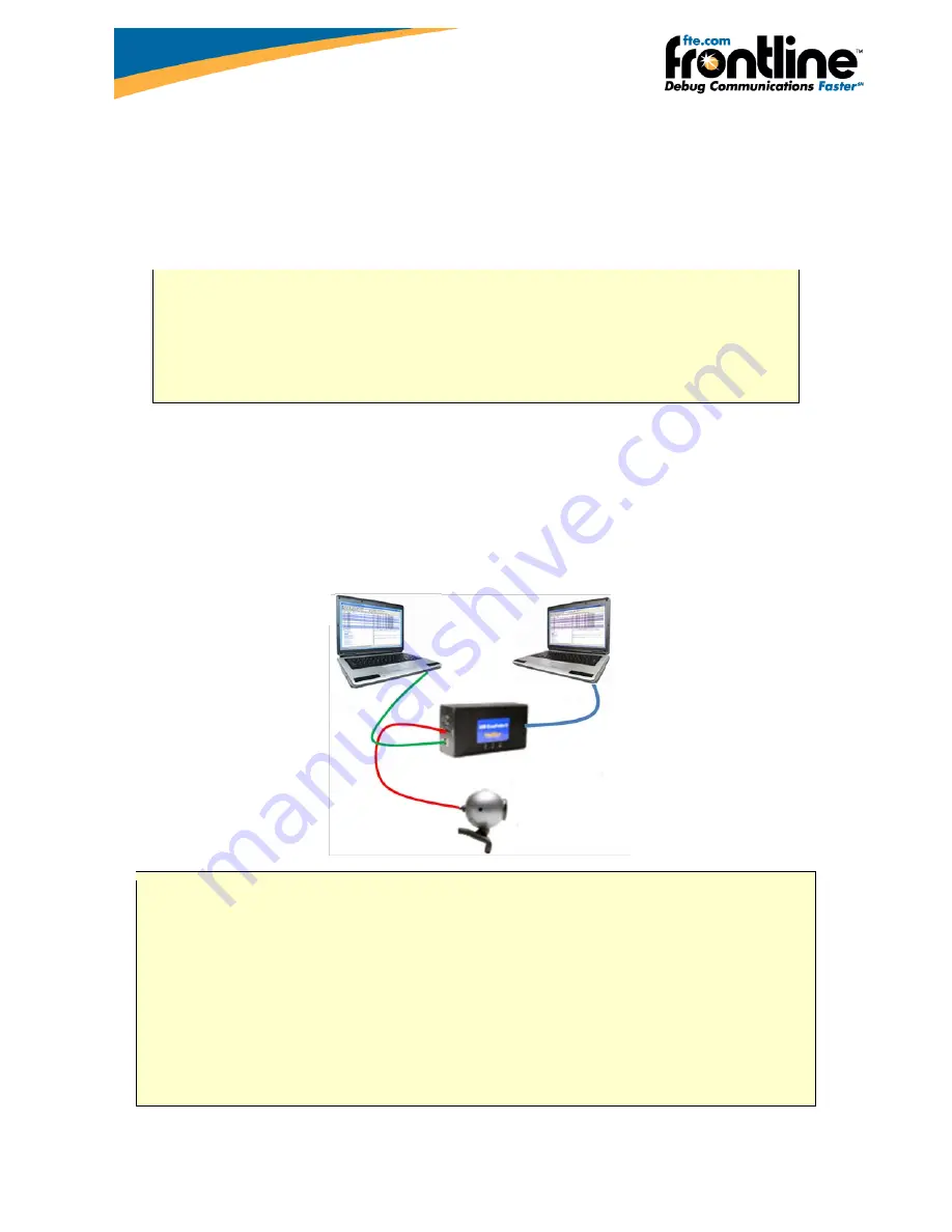
The most straightforward configuration involves only one device to be analyzed. Figure 2a shows how to 
properly connect the device under test.   


Figure 2a – Connecting only one Device Under Test (DUT) 


To prevent connection problems, please adhere to the following instructions: 


Make sure that 

NO USB DEVICE

 is plugged into the same root hub as the Device Under 

Test (DUT).   An extraneous USB device can result in FTS capturing data from the 
device, not the DUT. 


The Analysis computer cable must be no longer than 5 meters. 


The total length of the Test computer and Device Under Test cables must not exceed 3 
meters. A greater length could result in an abnormally high error rate on the bus being 
analyzed. 


Test Computer 

Analysis computer 

Device Under Test 

Содержание FTS4USB

Страница 1: ...or written authorization of Frontline Test Equipment Inc FTS Frontline Frontline Test System and ComProbe are registered trademarks of Frontline Test Equipment Inc FTS4BT is a trademark of Frontline T...

Страница 2: ...5 Connecting only one Device Under Test 5 Connecting more than one Device Under Test 6 Connection tips 7 Opening Selecting Data Capture Method 8 Capturing data 10 Analyzing Data 11 Control Window 11 F...

Страница 3: ...S PC with Windows XP 32 bit Service Pack 2 or higher Windows 7 32 and 64 bit Pentium 2 GHz processor RAM Requirements 2 GB minimum 50 MB free Hard Disk Space capture file size is limited only by disk...

Страница 4: ...ComProbe I USB Captures and decodes USB bus activities and transactions USB ComProbe II Bluetooth HCI Captures and decodes Bluetooth data USB and USB Setup data will be filtered out USB ComProbe II US...

Страница 5: ...onnection The front of the analyzer has three USB connections one for the device being tested one for the PC the device is normally connected to and one digital I O port Figure 1a Figure 1a Front Pane...

Страница 6: ...side also includes a mini DIN 9 connector which serves as a connection to the digital inputs and outputs Figure 1d Its pin outs and the cable coloring for the included cable are described in Figure 3d...

Страница 7: ...analyzer please ensure it is connected on a high speed USB 2 0 enabled host controller before contacting our technical support Connecting only one Device Under Test The most straightforward configurat...

Страница 8: ...evices this analysis must necessarily involve a USB hub In this way you can ensure that all the devices to be analyzed are in fact below the analyzer You should be aware that the analyzer will record...

Страница 9: ...ceed the recommended maximum lengths the cable connected to the analysis computer should not exceed 15 feet and the total length of the cables connected to the test computer and the device under test...

Страница 10: ...Start menu or from the Desktop folder 2 Select Frontline FTS4USB The Select Data Capture Method dialog appears Figure 3a Figure 3a Data Capture Methods Notice that the four sniffing methods that we i...

Страница 11: ...P a g e 9 3 Select one of the options 4 Select Run FTS4USB will open with the Control Window Figure 3b visible Figure 3b Control WIndow Now you are ready to begin capturing and analyzing data...

Страница 12: ...ill be cleared If you choose Cancel the dialog closes with no changes If you select the Clear icon while a capture is occurring The capture stops A dialog appears asking if you want to save the captur...

Страница 13: ...FTS4USB is organized around this window The Control window allows you to control data capture and access the other windows used to view data While there are a number of dialogs you can use to analyze...

Страница 14: ...gure 4c stretches across the top of the display Each line in the Summary Pane represents one frame except when running in one of the USB HCI Sniffing modes where each line represents one transaction F...

Страница 15: ...Frame Errors Frame numbers in red indicate an error in the frame Select the frame and look at the top of the Decode pane to determine the type of error Scrolling versus Static View Click the Lock Resu...

Страница 16: ...re updated with information such as the time the event occurred for data bytes the time the byte was captured the value of the byte in Hex Decimal Octal and Binary any errors associated with the byte...

Страница 17: ...start of an interaction in one Frame Display and the end of that same interaction in the other and compare the two Bookmarks Bookmarks let you mark frames of interest so they can be easily found later...

Страница 18: ...n common problems as well as software upgrades and utilities to use with our products Web http www fte com click Support Email tech_support fte com If you need to talk to a technical support represent...

Отзывы: