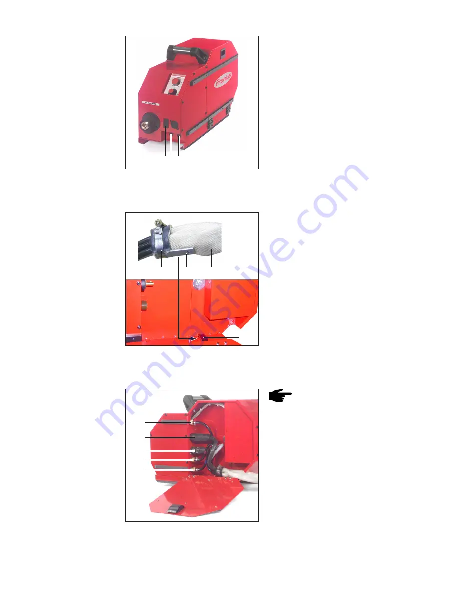
8
NOTE!
To prevent wear and tear,
form a loop towards the inside
when connecting the cables and
hoses of the interconnecting
hosepack.
1.
Plug the interconnecting hosepack
gas hose into the shielding gas
connection socket (1) and tighten
union nut
2.
Plug the welding potential cable of
the interconnecting hosepack into the
(+) current connection (2) and twist to
secure
Connecting the
interconnecting
hosepack to the
wire-feed unit
Connecting the interconnecting hosepack to the
wire-feed unit
3.
Plug the LocalNet plug on the inter-
connecting hosepack into the Local-
Net connection (3) and secure with a
union nut
(1)
(2)
(3)
(4)
(5)
Fitting the wel-
ding torch
(continued)
4.
If present, plug-in and lock the wel-
ding torch control plug to the torch
control lead connection (3) (option)
5.
If present, connect the water flow and
return connectors for the welding
torch to connections (4) and (5) of the
wire-feed unit
Welding torch activation and water connections
(option)
(3)(4)(5)
1.
Turn the power source mains switch
to the - O - position
2.
If present, allow the wire-feed unit to
engage with the swivel pin on the
swivel pin holder
3.
Remove cover on the right side of the
wire-feed unit
4.
Attach the metal piece (2) on the
interconnecting hosepack (3) strain
relief device (1) to the anchoring (4)
on the wire-feed unit
(3)
Fastening the strain relief device to the wire-feed
unit
Fastening the
interconnecting
hosepack to the
wire-feed unit
(2)
(4)
(1)


